I have a Yaesu FT-101E (late model) that initially had both transmit and receive problems but I've since corrected the receive issues with a thourough cleaning of the RL-1 and RL-2 relays. Now it receives as it should and will key and unkey properly. During the tune up process no i.c. value displays on the meter and adjusting the bias potentiometer has no effect. The meter does properly respond on receive and will move complete right when ALC is selected during the tuning process. 176vdc is present on pin 3 of the output tube sockets and the heaters work. I'm not sure if this is still potentially a relay issue or if there is somewhere else I should be looking at. Any help would be greatly appreciated. Thanks!

You are using an out of date browser. It may not display this or other websites correctly.
You should upgrade or use an alternative browser.
You should upgrade or use an alternative browser.
Yaesu: Yaesu FT-101E no transmit, no i.c.
- Thread starter Champo
- Start date
- Status
- Not open for further replies.
It's been a very long time for me but sounds like Relay 1.
prcguy
Member
How about HV? There should be a good 700+ volts on the PA tubes during transmit.
I do not have HV at the tube sockets. The tubes (driver + PA) are out at the moment though so if they need to be in place let me know and I will reinstall them.How about HV? There should be a good 700+ volts on the PA tubes during transmit.
prcguy
Member
I can't remember the exact tube used in your version but the 700+ volts would be on a plate cap with flying lead and you don't need the tube installed to read it but I would for safety reasons.
I do not have HV at the tube sockets. The tubes (driver + PA) are out at the moment though so if they need to be in place let me know and I will reinstall them.
The PA tubes are 6JS6C's. I do not have HV on any of the pins on the socket during transmit. I've included the tube data sheet and a picture of the bottom of the tube socket. If you need the values from the other pins I can get it. There was nothing above the 173 on pin 3 I believe it was.
Attachments
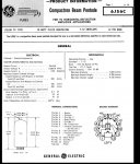
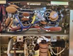
Plate voltage is supplied by the flying lead connected to the 'button' on top of the tube(s).
My mistake. I will check that. Thank you for the correction.Plate voltage is supplied by the flying lead connected to the 'button' on top of the tube(s).
I do have HV (700Vdc).My mistake. I will check that. Thank you for the correction.
prcguy
Member
If the PA tubes have filament, HV and bias, they should draw some current or I.C. on your meter and vary with the bias control even without RF drive. If all voltages are there it sounds like a problem in the metering circuit or shunt resistors that feed the meter circuit or any switching in line with the meter circuit like a relay.
It sounds like everything has come back to that relay. I figured that even if the meter wasn't reading the bias properly there would still be some output of some sort with the carrier adjustment (as registered on an external watt meter) but there was none at all. Is this a false assumption? Also am I understanding correctly? If not I apologize. I appreciate your help and patience.
prcguy
Member
Old relays can be a big PIA so even though you cleaned it, don't rule it out as the culprit. Sometimes I use a relay contact burnishing tool on the contacts and more recently some thick paper soaked in Deoxit D5 solution. I close the contacts on the paper then pull it through several times under the contacts spring tension. You will usually see some black oxide come off on the first pass and that will tell you the contacts are probably mating ok.
Sometimes relays need mechanical adjustment for tension and alignment which can easily go wrong. You can also use a volt meter and ohm meter to see if the contacts are working. With power off you can probe both sides of the contacts with an ohmmeter to see if its 0 ohms when making contact. When powered up you can use a volt meter to see voltage across the contacts when they are open and it should go to 0 volts when they make contact. This is on contacts with voltage and some do not have a measurable voltage. You just have to probe everything until your convinced the contacts are making electrical contact or not.
Sometimes relays need mechanical adjustment for tension and alignment which can easily go wrong. You can also use a volt meter and ohm meter to see if the contacts are working. With power off you can probe both sides of the contacts with an ohmmeter to see if its 0 ohms when making contact. When powered up you can use a volt meter to see voltage across the contacts when they are open and it should go to 0 volts when they make contact. This is on contacts with voltage and some do not have a measurable voltage. You just have to probe everything until your convinced the contacts are making electrical contact or not.
It sounds like everything has come back to that relay. I figured that even if the meter wasn't reading the bias properly there would still be some output of some sort with the carrier adjustment (as registered on an external watt meter) but there was none at all. Is this a false assumption? Also am I understanding correctly? If not I apologize. I appreciate your help and patience.
OK I think we're on the same page. Yeah I used card stock soaked in deoxit which got my receive back but then it would hang up when placed into MOX. I followed up with card stock soaked in 91% alcohol which solved the hang up issue but the no i.c. has been constant. The new relay seems to be the key so hopefully that will correct it. Thank you for all of the help. I'll let you know how it goes on Tuesday. Fingers crossed lol!
prcguy
Member
I would offer you my FT-101 for parts but it p*ssed me off so bad I used it as a 100yd target.
Here is what was left of the insides. A little Deoxit spray might have brought it back but I didn't have any with me.

Here it is before final roasting on the camp fire.

Here is what was left of the insides. A little Deoxit spray might have brought it back but I didn't have any with me.
Here it is before final roasting on the camp fire.
Well I discovered that functional tubes need to be installed in order to get an i.c. value on the meter. The second thing I discovered is the PA tubes in mine were dead. The radio is currently operating. The steps I went through are as follows:
1. Installed new relay and tested without all three tubes - no i.c. value
2. Installed new PA tubes and old driver tube with new relay - FUNCTIONAL RADIO
3. Installed old PA tubes with new relay - no i.c. value
I'm not sure if the new relay played a role in all of this i.e. multiple problems or not but I did not reinstall the old relay with the new tubes since I do not want to put the new tubes in potential jeopardy. I want to thank everyone for their help and advice through this. I also have one quick question on where the i.c. value should be on the meter after tuning. Should it be in the white, the green or is it irrelevant? Again thank you everyone for your help!
Well that was short lived. Now, after running through the receive tuning I'm having an issue with loading. When you adjust the loading knob you no longer hit a peak and then dip. Now it increases until the knob bottoms out at 10 with no dip. Output increase is minimal during loading. Output has been cut by more than half. It went from about 70 watts out to about 30. Are the tubes dying on me or is there something else at play? Thanks.
prcguy
Member
Typically its the TUNE knob that dips the plate current then the LOAD knob that matches the load and you over couple it slightly for stability. Or do you under couple, I forget? Anyway the plate current can go through the roof during tune up and if there is a green line target for plate current or i.c. that should be after its dipped to its lowest value.
Well that was short lived. Now, after running through the receive tuning I'm having an issue with loading. When you adjust the loading knob you no longer hit a peak and then dip. Now it increases until the knob bottoms out at 10 with no dip. Output increase is minimal during loading. Output has been cut by more than half. It went from about 70 watts out to about 30. Are the tubes dying on me or is there something else at play? Thanks.
I might not be explaining it in the right way. Let me try again. During the PO tune up process it has you key with the carrier at 4 and then adjust the preselect for max output. Then adjust the loading for max output. Then adjust the plate for max output. Then repeat with carrier at 6, 8 and finally 10. Yesterday it would adjust preselect for max, then the loading for max which kept it around 3-4 level before the dip and then pull it back to peak. Rinse, repeat with the carrier increase. Today though it tuned up just fine earlier in the day and then I powered her off and went about my business. Later I came back and ran through the tuning sequence but once I got to the loading phase, rather then peaking and then a dip and then bringing it back to its max I barely got any increase and that increase happened from around 3-4 all the way to 10. Long story short, it isn't doing what it was doing before. As a result output has decreased to a 3rd of what it was.
- Status
- Not open for further replies.
Similar threads
- Replies
- 0
- Views
- 410
- Replies
- 0
- Views
- 414
- Replies
- 2
- Views
- 522
- Replies
- 48
- Views
- 9K