Yagi antennas for under $5

Status
Not open for further replies.

n211cr

Member
Joined
Mar 14, 2004
Messages
189
Location
Owosso or East Lansing, Michigan
I just built one over the last few days from a 1x2 and the coat hangers. It does seem to work fairly well.

What seems to be the best solution to keep a good contact with the aluminum shielding with any surface really but especially the steel coat hangers?
 

wesm1957

Member
Premium Subscriber
Joined
Jan 20, 2005
Messages
315
Location
Otsego, MI
I built this yagi this week and it made a world of difference on how well I can pick up 800mhz now. I live in an apartment and an outside antenna is out of the question. This one has a 9 inch boom and was made for a center frequency of 868mhz. i got all my measurements here:

http://www.dxzone.com/cgi-bin/dir/jump2.cgi?ID=11183

I have another ready to put together and I am going to try it by making the driven element a dipole. Here are a few pictures of mine temp. mounted on my radio stand.

Wes
 
Last edited:

tripleplay905

Member
Joined
Jan 5, 2006
Messages
86
Location
Summit Co, Ohio
Great antenna. I have a question tho. It looks like you only connected the center of the coax to the driven element. Where then did you connect the shield too? Thanks.
 

wesm1957

Member
Premium Subscriber
Joined
Jan 20, 2005
Messages
315
Location
Otsego, MI
tripleplay905 said:
Great antenna. I have a question tho. It looks like you only connected the center of the coax to the driven element. Where then did you connect the shield too? Thanks.

The shield is connected to the boom. The directors and reflector elements are 1/8 brass rod and the driven is 1/16. It is insulated from the boom with a plastic tube and held in place with CA glue.

Wes
 

kb9hgi

Member
Feed Provider
Joined
Jun 17, 2003
Messages
496
Location
IL
Where is the plans for the 800mhz yagi? I want to build one of those.
 

k8tmk

Member
Joined
Jan 13, 2004
Messages
316
Location
Stevensville, MI
The director and reflector elements of a yagi are called "parasitic elements." It does not matter if they are connected to anything or not. What is critical about them is their lengths and spacing between each other and the driven element.

Wesm1957 indicated that he connected the shield to the boom. Somehow that sounds very strange to me. The driven element typically works like a dipole and has both the "hot" lead and the shield lead connected to it. The two halves of the driven element can be insulated from each other and the boom, or they can be one piece, still insulated from the boom, if you use a matching device like a "gamma match."

I built an 800 MHz yagi from a year-old Popular Communications magazine article. It works great!

Randy
 

bagged2000

Member
Joined
Nov 14, 2008
Messages
8
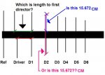
I have a question. If i am going to build an 800mhz version of this. On your chart showing the space between the driver and the first director... Since the driver is actually 2 pieces spaced a half cm apart. where does the first director actually start compared to the reflector. and also are the lenghts of the reflectors/driver/and directors on the chart including the portion of the wire inside the beam. heres my questions like a 4th grader would probably ask...

Thanks
Drew
 

Attachments

  • questions.JPG
    questions.JPG
    31 KB · Views: 1,795

Sinister

Member
Premium Subscriber
Joined
Sep 5, 2008
Messages
350
Location
New Hampshire
I have a question. If i am going to build an 800mhz version of this. On your chart showing the space between the driver and the first director... Since the driver is actually 2 pieces spaced a half cm apart. where does the first director actually start compared to the reflector. and also are the lenghts of the reflectors/driver/and directors on the chart including the portion of the wire inside the beam. heres my questions like a 4th grader would probably ask...

Thanks
Drew

Looking at the instructions:
1) All spacing is from the previous element not the reflector so the spacing in your question would be 6.1507 cm from the driven element to D1.
2) On the Driven element it is 1/2 the length given plus the thickness of your beam. ie.. 16.8 divided by 2 = 8.4 cm then add thickness of boom= length of driven element for each side.
In all lengths given for the elements you must add the thickness of the boom your using.

The question I have on this project is if I add a 300 ohm to 75 ohm matching transformer does the driven element need to be cut.
 
Last edited:

k9rzz

Member
Joined
Dec 12, 2005
Messages
3,162
Location
Milwaukee, WI
The question I have on this project is if I add a 300 ohm to 75 ohm matching transformer does the driven element need to be cut.

What's your plan? A folded dipole driven element (300 ohm) with 75 ohm feedline? or standard driven element (75 ohm) with 300 ohm feedline?

Adjust the driven element for resonance to a certain frequency, adjust the feed for impeadance matching.
 

Sinister

Member
Premium Subscriber
Joined
Sep 5, 2008
Messages
350
Location
New Hampshire
What I ended up doing was cutting the driven element, and mount one at the specified spacing the other 3/16" forward from that. Will be using RG6 to connect to driven element. The driven element is set at the resonance frequency of 850 Mhz. I take it there is a formula for calculating the impedance of the feed for matching or is this even necessary.
 

lbfergus

Member
Premium Subscriber
Joined
Sep 12, 2008
Messages
39
Location
Salem, OR
So I guess I still don't understand how the cable is connected to the antenna. Can someone shed some light on it, I think I would like to build one of these this week.

Thanks,
Levi
 
Status
Not open for further replies.
Top