
You are using an out of date browser. It may not display this or other websites correctly.
You should upgrade or use an alternative browser.
You should upgrade or use an alternative browser.
Looking for the pinout for the GPS interface on the SDS100
- Thread starter W2GLD
- Start date
- Status
- Not open for further replies.
They are USB.

Jon: Check your PM.
I just realized that you were talking about the USB-mini connector where power and programming are also performed; what I was actually hoping/looking for was for the secondary USB-micro connector to see about putting GPS there. I had assumed that this connector is what replaced the older style one Uniden was using on the BCDx series scanners. Is this not the case?
I don't believe the micro can be used for GPS.
Hit_Factor
Member
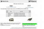
The jacks are standard USB mini and micro and the pinouts are widely available online.
The only quirk is that the GPS input goes to the ID pin (next to ground) of the USB mini jack.
Could you clarify that using the pin numbers from the picture? My GPS only has 4 wires.
The vast majority of USB Mini-B cables never connect the ID pin to a wire.
Hit_Factor
Member
Do you know which wire goes to the ID pin? My GPS has red, black, white , green, bare w/ shield.
I order some of the connectors Jon listed along with some USB A male. My plan is wiring the male A for 5vdc on a separate leg. In other words, The gps wires to the micro usb and 5vdc coming in from the male A. Of course I still need to figure out the wiring.
It seems that red/black are the 5vdc. But what are the white/green/bare?
Hit_Factor
Member
Thanks Jon,
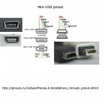
I'm still trying to figure out your comment on post #3 "The only quirk is that the GPS input goes to the ID pin (next to ground) of the USB mini jack"
ID is pin 4, which wire is this?
I'm still trying to figure out your comment on post #3 "The only quirk is that the GPS input goes to the ID pin (next to ground) of the USB mini jack"
ID is pin 4, which wire is this?
Thanks Jon,
I'm still trying to figure out your comment on post #3 "The only quirk is that the GPS input goes to the ID pin (next to ground) of the USB mini jack"
ID is pin 4, which wire is this?
Connect the data coming from the GPS to that ID pin.
Hit_Factor
Member
GlobalSat BU-353S4, I cut of the serial to USB end (uses the prolific driver)
So instead of instead of going to D+, solder tx to ID?
So instead of instead of going to D+, solder tx to ID?
Is 5v available out on any of those ports? I assume not.
GlobalSat BU-353S4, I cut of the serial to USB end (uses the prolific driver)
So instead of instead of going to D+, solder tx to ID?
You need the straight serial version..
GlobalSat BR-355S4 GPS
http://a.co/cNSwGaX
Hit_Factor
Member
When I plugged the GPS into the scanner with a conversion cable the GPS was not powered. When I plug the GPS into a USB power source it powered up.
I'm planning on no power at the port, and charging the scanner when I have the GPS plugged in.
I'm planning on no power at the port, and charging the scanner when I have the GPS plugged in.
Hit_Factor
Member
Do i have the equivalent now that I cut off the prolific chipset/USB plug?
I am not sure about that..
Sent from my Pixel XL using Tapatalk
Sent from my Pixel XL using Tapatalk
- Status
- Not open for further replies.
Similar threads
- Replies
- 19
- Views
- 754