BC350C discriminator tap?

Status
Not open for further replies.

dummygun

Member
Joined
Feb 10, 2005
Messages
4
Hi guys I would like to know if it is possible to put a discriminator tap in a BC350C and if yes where to to hook it up ive been looking in several forums and websites for answers but cannot find the guide for the this model .If legal iam planning on building a slicer for it and eventually when iam rich and famous i would like to get a second scanner for the sytem thats able to trunktrack .. You guys got a kewl forum going on over here btw ..

eric
 

thumbtrap

Member
Joined
Aug 6, 2004
Messages
235
Location
At my computer, duh!
I've not done it, but I looked in, found the discriminator ic, found that it is a common one, but not the same as the 350A, and then forgot what it was.
So... you'll have to do your homework, but it's there - it's not buried under the epoxy globs, and if you can match it, you ought to be able to proceed from the instructions for the appropriate IC from there.
 

dummygun

Member
Joined
Feb 10, 2005
Messages
4
hmm in the 350a its ic NJM-3359D-A Your right ..Ive been looking for that chip since i thought the only diffrence between the 350a and 350c version is the the 800mhz band..but i could not find that ic..What i did find is the Tda 1905 what is a 5 watt audio amplifier with muting. Ic6 is half burried under epoxy so know idea what that one is....Then on the bottom/top of the board 3361D01..Is that the on??? ..Thanks for the help thumbtrap ..

eric
 

k7icu

Member
Joined
Aug 3, 2004
Messages
7
Location
Tucson, AZ
So it looks like this thread is a little old, but I just tore into a BC350C and wanted to share a couple things not mentioned previously:

There are a couple things about pin 9 of that 3361 chip that may be a problem depending on what you're interfacing to.

1) There's just as much 455 kHz IF present on that pin as any other audio. You can get rid of it with a simple RC filter:

Discriminator Output AE65H - COM212 - BC60XLT

He used a 12k resistor and a 2.7nF cap for a cutoff around 4900 Hz. I had a 15k resistor and 2.2nF cap at the time so I used those for a cutoff around 4800 Hz. Close enough considering the response of this type of filter.

A nice and quick online RC filter calculator is right here:

Guitar Pedals: R-C Filter Calculator

2) There's about 1.5VDC on pin 9 too. I take care of that with a series .01uF ceramic cap when necessary.

The page at the URL referenced earlier in the thread is gone, but it's archived here:

http://web.archive.org/web/20050212094123/http://home.hvc.rr.com/bpetrow/discrim.txt
 

k7icu

Member
Joined
Aug 3, 2004
Messages
7
Location
Tucson, AZ
How low?

I just observed a sine wave put through a .01uF ceramic cap from 100 Hz to 5 kHz. No distortion. No attenuation. I even dropped it down to 100mV for some extra noise. Looks the same coming out as it does going in.
 

slicerwizard

Member
Joined
Sep 19, 2002
Messages
7,643
Location
Toronto, Ontario
A tap should pass audio down in the 2 to 10 Hz range with no distortion or attenuation.

15 consecutive 0 or 1 bits at 300 bps would be a 10 Hz signal if the waveform was a pure sinewave. Since it isn't, the signal contains frequency components well below 10 Hz.
 

k7icu

Member
Joined
Aug 3, 2004
Messages
7
Location
Tucson, AZ
Your typical AFSK modulated carrier at 300 bps or 1200 bps uses a 1200 Hz mark and a 2200 Hz space (or a variation in that general area). It's not unusual to see such stuff interfaced to microphone inputs and speaker outputs, neither of which can really be expected to pass audio below 300 Hz.

What am I missing?
 

slicerwizard

Member
Joined
Sep 19, 2002
Messages
7,643
Location
Toronto, Ontario
The encoding methods you refer to generally don't need a discriminator tap to decode.

I'm referring to straight FSK, where typically two or four RF frequencies (+/- shifts from the center frequency) are used to directly represent two or four logic states / symbols, e.g. 0 or 1, or 00, 01, 10 or 11.

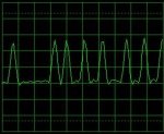
While the RF transmitter is sending a particular symbol, the receiver's discriminator point will (for the most part) maintain a matching voltage level. As shown in the attached image, when the transmitter sends a string of zero bits, the tap point is held low for an extended period; a .01 uF cap is not going to pass that signal - it will quickly start charging and the load (your soundcard) will see a signal that instead of being flat (as shown), will ramp towards the zero / center line as the cap's voltage level approaches the discriminator's voltage level.

That will cause a decoding application to see the zero crossing too early, which leads to errors in tracking bit edge timing, which leads to flipped (incorrect) bits. It doesn't take too many of them to defeat the FEC used in some of the common protocols. Some don't even have FEC, just error detection, so a single flipped bit means a lost data block.

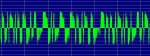
That image shows what my sound card sees; its hardware, along with the various sound cards / laptop internal audio devices I've used over the last ten years, have never had a problem dealing with the low frequency components found in FSK signals. That's not to say that there aren't a few stinkers out there, but they seem to be rare.
 

Attachments

  • 3600 bps CC.JPG
    3600 bps CC.JPG
    16.2 KB · Views: 812

slicerwizard

Member
Joined
Sep 19, 2002
Messages
7,643
Location
Toronto, Ontario
This image shows what an undersized cap will do to FSK signals - the longer the discriminator voltage is held high or low, the more the cap charges up and the sound card sees a signal that ramps towards the center line.

Note how the long 0 or 1 strings unbalance the signal - the relatively quick transitions at the left side of the image keep the positive peaks at their normal level (about one line below the major white line), but when the long strings of zero bits show up, the positive peaks shift right up to the thicker white line. That causes the 0-->1 crossing to be seen early and the following 1-->0 crossing to be seen late. A signal that was actually high for say, 3 bit times, now looks like it was high for 4 bit times. That can easily lead to a decoder seeing one too many '1' bits by flipping an adjacent zero bit. With bits being flipped whenever a long enough sequence of zeroes or ones come along (the more undersized the cap, the fewer consecutive bits required), FEC fails and you start losing 5, 10, 20% of the blocks in the datastream.
 

Attachments

  • Undersized Cap.JPG
    Undersized Cap.JPG
    33 KB · Views: 934

k7icu

Member
Joined
Aug 3, 2004
Messages
7
Location
Tucson, AZ
Well I guess I've never run into this because I've only played with AFSK.

After some more experimenting, I can say:

Input impedance of whatever you're interfacing to makes a big difference. 20 Hz through .01uF shows some attenuation even into 1M-ohms, and it bombs out at 600-ohms. With 0.1uF, we're good into 1M-ohms, but still way too low into 600-ohms. I reached 20uF before 20 Hz into 600-ohms was OK. (That may not be enough even, but my generator bottoms out at 20 Hz).

A sound card mic input could be 600-ohms, but I don't think we're using that for FSK nowadays...

I can't speak for the distortion issue, but I suspect a relationship with attenuation.

Looks like most of the FSK data slicers out there already have a .1uF cap just before a 1M-ohm+ input.
 
Last edited:
Status
Not open for further replies.
Top