Ubbe
Member
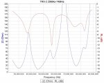
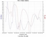
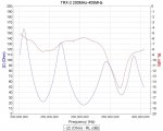
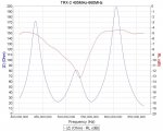
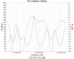
Some plots of the impedance (blue curve) at different frequencies. This is the impedance that the coax, or the direct connected antenna, sees at the scanner end.
TRX-2 have 5 different filters for different frequency ranges. The RL Return Loss value suggest with its lowest value where the filter is tuned and passes the signal best.
/Ubbe
TRX-2 have 5 different filters for different frequency ranges. The RL Return Loss value suggest with its lowest value where the filter is tuned and passes the signal best.
/Ubbe