Building Off Center Dipole. Balun or No Balun? And Related Questions

Status
Not open for further replies.

MVUSA

Member
Premium Subscriber
Joined
Sep 12, 2011
Messages
25
Location
Northern California
I am using a BCT15X scanner, and I like listening to various things in the 150, 450 and 850 range.

Currently I am using a C.Crane Coaxial Scanner Antenna
http://www.ccrane.com/antennas/scanner-antennas/coaxial-scanner-antenna.aspx?ProdEdp=12026
This antenna does not have a balun.

I would like to build an improved version of this, if that is possible.
So, would I just get some LMR400 and duplicate this current antenna?
Duplicate it with LMR400, but use a balun like a Channel Master CM 94444?

Many other questions, but I will hold off…

I appreciate the help and advice.
 

Attachments

  • coaxial-scanner-antenna.gif
    coaxial-scanner-antenna.gif
    18.8 KB · Views: 8,638

LtDoc

Member
Joined
Dec 4, 2006
Messages
2,145
Location
Oklahoma
No balun is needed, the antenna is 'unbalanced' to start with. Considering the short feed line run, I think LMR-400 would be a waste of time and money. If your particular installation is as pictured (doubt it) the best improvement you could make is to move the antenna outside and get it as high as possible. Swapping the long end so it's up might help too, just means at least part of that antenna is higher.
Have fun.
- 'Doc
 

ampulman

Member
Joined
Aug 18, 2006
Messages
915
Location
South Jersey
Since there is no technical description on the Crane web page, I question whether this is a true 'coaxial' antenna or a simple OCD.

Make it easy on yourself, don't bother with coaxial cable; use simple wire instead. Or, as I did, a pair of rabbit ears (type that comes with a tv (not a stand-alone). One advantage, when monitoring a single frequency, poles can be adjusted to form a simple dipole, tuned (within limits) to the monitored frequency.

Amp
 

MVUSA

Member
Premium Subscriber
Joined
Sep 12, 2011
Messages
25
Location
Northern California
No balun is needed, the antenna is 'unbalanced' to start with. Considering the short feed line run, I think LMR-400 would be a waste of time and money. If your particular installation is as pictured (doubt it) the best improvement you could make is to move the antenna outside and get it as high as possible. Swapping the long end so it's up might help too, just means at least part of that antenna is higher.
Have fun.
- 'Doc

My total feed line would be about 25 feet, which I believe you would still consider short.
Unfortunately, I can’t mount an antenna outside right now.

Also, just thought of this last night. Wouldn’t copper be better than aluminum?
I say this since I realized that the LMR400 is Solid Copper Clad Aluminum Center Conductor and Double Shielded. First Shield: Bonded aluminum foil with 100% coverage and Second Shield: Tinned copper braid with 98% coverage.

So maybe I should use a copper wire and braid coax like a RG-213/U for the antenna. Then use the LMR400 as my feed line. Then that’s where I don’t know how to connect the 2 together.

Thanks for the reply.
 

MVUSA

Member
Premium Subscriber
Joined
Sep 12, 2011
Messages
25
Location
Northern California
Since there is no technical description on the Crane web page, I question whether this is a true 'coaxial' antenna or a simple OCD.

Make it easy on yourself, don't bother with coaxial cable; use simple wire instead. Or, as I did, a pair of rabbit ears (type that comes with a tv (not a stand-alone). One advantage, when monitoring a single frequency, poles can be adjusted to form a simple dipole, tuned (within limits) to the monitored frequency.

Amp

I know that’s kind of a problem. I have no idea what this coax is that they are using.
Not sure what the difference is between a true coaxial and simple OCD.

They are using the center conductor as the short part of the antenna, and the braid shield for the long part of the antenna.

Since they are doing it this way, isn’t the feed line part of the antenna as well? I guess it could be bad or good. Would you have the possibility of receiving lower frequencies this way?

Thanks for the reply.
 

nanZor

Active Member
Joined
May 28, 2009
Messages
2,807
I can see the confusion between this and the OCFD, which I have used quite a bit, with some precautions.

If you want to build an OCFD, then YES, a balun is necessary. BUT, what you are really using is the 4:1 transformer part of the balun. The impedance of an OCFD flucuates between about 200 ohms and 500 ohms or so depending on frequency.

The actual antenna is really primarily on 88 mhz, and by using an offset with the transformer, you can get reasonable multi-band use out of it, BUT you can get some funky lobes as you go higher in frequency. This may not matter in a metropolitan situation - BUT another but! This broadband performance may not be desired in a metro area! Talk about catch-22. :)

88 mhz is the primary frequency this thing is cut for! Typically one uses 1.5 feet of wire/tubing on one side of the 300-ohm terminals, and 4 feet on the other side of the 300 ohm terminal. Put together, this makes for a nice FM broadcast antenna in its own right - something you may not want if you suffer FM broadcast desense.

As for the "balun" part of it, the antenna itself is so electrically unbalanced, that a typical TV-type 4:1 balun is not doing ANY "baluning" at all! :) Just the impedance transformation. Some have put snap-on chokes near the feedpoint to play with it.

This means that there is considerable common-mode current along the outer skin-depth of the braid - which actually helps low-band VHF - however that is pretty much a random wire electrically as it snakes around your installation. Officianados of low-band VHF have tried putting snap-on chokes a quarter-wave down the coax from the feedpoint to kind of help low-band vhf even more.

However, they are easy to make with just some wire, a cheap 300:75 ohm transformer, and some clips behind a window curtain for temporary hanging. This makes it easy to do a test-run before building something more substantial.

Another catch is that if you use a long run of coax, and with the 800 mhz SWR not being ideal, you can suffer from the additional SWR loss with lossy coax. That, along with the weird lobes may not make it ideal for 800mhz. You COULD run some really nice low-loss coax to help out, but I've never heard of anyone running good stuff to an OCFD. But yes, overall low-loss coax would be beneficial.
 
Last edited by a moderator:

MVUSA

Member
Premium Subscriber
Joined
Sep 12, 2011
Messages
25
Location
Northern California
I can see the confusion between this and the OCFD, which I have used quite a bit, with some precautions.

If you want to build an OCFD, then YES, a balun is necessary. BUT, what you are really using is the 4:1 transformer part of the balun. The impedance of an OCFD flucuates between about 200 ohms and 500 ohms or so depending on frequency.

The actual antenna is really primarily on 88 mhz, and by using an offset with the transformer, you can get reasonable multi-band use out of it, BUT you can get some funky lobes as you go higher in frequency. This may not matter in a metropolitan situation - BUT another but! This broadband performance may not be desired in a metro area! Talk about catch-22. :)

88 mhz is the primary frequency this thing is cut for! Typically one uses 1.5 feet of wire/tubing on one side of the 300-ohm terminals, and 4 feet on the other side of the 300 ohm terminal. Put together, this makes for a nice FM broadcast antenna in its own right - something you may not want if you suffer FM broadcast desense.

As for the "balun" part of it, the antenna itself is so electrically unbalanced, that a typical TV-type 4:1 balun is not doing ANY "baluning" at all! :) Just the impedance transformation. Some have put snap-on chokes near the feedpoint to play with it.

This means that there is considerable common-mode current along the outer skin-depth of the braid - which actually helps low-band VHF - however that is pretty much a random wire electrically as it snakes around your installation. Officianados of low-band VHF have tried putting snap-on chokes a quarter-wave down the coax from the feedpoint to kind of help low-band vhf even more.

However, they are easy to make with just some wire, a cheap 300:75 ohm transformer, and some clips behind a window curtain for temporary hanging. This makes it easy to do a test-run before building something more substantial.

Another catch is that if you use a long run of coax, and with the 800 mhz SWR not being ideal, you can suffer from the additional SWR loss with lossy coax. That, along with the weird lobes may not make it ideal for 800mhz. You COULD run some really nice low-loss coax to help out, but I've never heard of anyone running good stuff to an OCFD. But yes, overall low-loss coax would be beneficial.


A lot of good info, too bad I don’t really understand most of it.

So, I’m still not sure if I want to build like I have now with better materials, or one real OCFD.

If I did build one like I have now, how, what would I use to connect the antenna portion to the feed line portion?

(Slight ramblings about that)
If I wanted to make an exact duplicate of what I have now but with better materials (i.e.: RG-213/U for antenna portion and LMR400 for the feed line), then I would just use coax connecters to connect the antenna and feed line. Which would make the feed line part of the antenna, but then that may or may not be a bad thing. Or if I was going to use something else to connect the antenna and feed, it might as well be a balun to make it a real OCFD?

Also, I live in a rural area. Nearest, small town is 15 miles away. Next is 20 miles, then 30 miles, and so on…
Also, there are great elevation changes between towns as well. A generalization of the elevation changes would be 1000 to 1500 feet differences.

Thank you for the reply.
Hope my words are making sense. Been up for a few days, driving back from a road trip.
 

nanZor

Active Member
Joined
May 28, 2009
Messages
2,807
Or if I was going to use something else to connect the antenna and feed, it might as well be a balun to make it a real OCFD?

Honestly, with this antenna, I would keep it simple as possible at first for evaluation. The LMR400 is a great idea, but honestly, with only a 25 foot run, and an antenna that is not proven to actually work well in your situation, here is what I'd do:

1) Use RG-6 tv-type coax for the transmission line. Something like the 25-foot Radio Shack #15-1534 will do. Save the LMR400 for a "real antenna". :)

2) Grab either a Radio Shack #15-1140 or #15-1230 tv-type 300:75 ohm transformer/balun. I just use RS as a convenient reference, not a preference. :) These are NOT combiner/splitters, just simple 300:75 ohm transformers.

3) Use a dual-row barrier strip such as #274-656 to attach the twinlead portion of the transformer to, and also to attach the 1.5 foot and 4-foot antenna wires. The twinlead of the transformer will come in sideways to the barrier strip, and the wires bent vertically.

(You could also use a convenient cube-type #15-1253, but you'd need to run several adapters - the one above reduces using a mess of adapters.)

4) Grab an F-to-BNC adapter for the radio end. I see a #278-277. This is gold-plated, so you may want to opt for a standard one instead, but I didn't see the standard one.

5) Run the coax away from the antenna wires horizontally for at least a few feet, and then snake it around your location.

Also, I live in a rural area. Nearest, small town is 15 miles away. Next is 20 miles, then 30 miles, and so on…
Also, there are great elevation changes between towns as well. A generalization of the elevation changes would be 1000 to 1500 feet differences.

This is why I think making a test run out of the simplest materials might be best to determine if an OCFD will even really be usable in the long run with better stuff. The lobes at 800mhz might be so bad that even using LMR 400 won't fix it! :)
 
Last edited by a moderator:

MVUSA

Member
Premium Subscriber
Joined
Sep 12, 2011
Messages
25
Location
Northern California
Honestly, with this antenna, I would keep it simple as possible at first for evaluation. The LMR400 is a great idea, but honestly, with only a 25 foot run, and an antenna that is not proven to actually work well in your situation, here is what I'd do:

1) Use RG-6 tv-type coax for the transmission line. Something like the 25-foot Radio Shack #15-1534 will do. Save the LMR400 for a "real antenna". :)

2) Grab either a Radio Shack #15-1140 or #15-1230 tv-type 300:75 ohm transformer/balun. I just use RS as a convenient reference, not a preference. :) These are NOT combiner/splitters, just simple 300:75 ohm transformers.

3) Use a dual-row barrier strip such as #274-656 to attach the twinlead portion of the transformer to, and also to attach the 1.5 foot and 4-foot antenna wires. The twinlead of the transformer will come in sideways to the barrier strip, and the wires bent vertically.

(You could also use a convenient cube-type #15-1253, but you'd need to run several adapters - the one above reduces using a mess of adapters.)

4) Grab an F-to-BNC adapter for the radio end. I see a #278-277. This is gold-plated, so you may want to opt for a standard one instead, but I didn't see the standard one.

5) Run the coax away from the antenna wires horizontally for at least a few feet, and then snake it around your location.

Thank you very much for the detailed build info! Including parts and numbers!
I will have to give this a try.

This is why I think making a test run out of the simplest materials might be best to determine if an OCFD will even really be usable in the long run with better stuff. The lobes at 800mhz might be so bad that even using LMR 400 won't fix it! :)

I will definitely do some test runs. Different lengths of antenna’s?

A place of listening interest at freq 155 is about 800 – 1500 above me, depending on the repeater.
Also a 150-155 Trunked LTR Standard system is up there as well.
Other listening interests are 1100 feet below me.

Like I said before I am trying to magically pull in everything i.e.: 150 – 450 – 850, well you get the idea. Just wonder or maybe I’ll find out, if there are some sweat spots for antenna lengths to achieve this.

Thanks again.
 

LtDoc

Member
Joined
Dec 4, 2006
Messages
2,145
Location
Oklahoma
Some things to be aware of.
An OCFD is a 1/2 wave length at the lowest frequency of use, if it's to be 'multi-banded'. The reason for the thing being fed at an 'off center' point is to change the input impedance from something close to 75 ohms to something close to 50 ohms. If that point is picked correctly, the same 'ratio' will work for most bands. The antenna is NOT balanced so doesn't require the use of a balun when using coaxial cable for the feed line. If you want to use something for changing the impedance (like some baluns do) then use an 'Unun', unbalanced to unbalanced transformer of the correct impedance changing ratio. That's going to be a real trick! How do you select the right transformation ratio? It will NOT be the same for all bands.
Using copper instead of aluminum? It's just not worth the bother, there isn't enough difference in 'conductance' to make any difference at all. Hey! (Use gold instead?)
How about using coax as the conductors of that antenna? Why? About the only difference would be conductor diameter. Not enough benefit to make it worthwhile (in my opinion).
I think a possible solution for a multi-band antenna would be something on the order of a 'fan' dipole. One 1/2 wave dipole for each band with all their feed points connected to the same point. 'Fan' them out a little to keep the interaction as little as possible. And the absolute best improvement for any VHF/UHF antenna is more height. (Take a look at the 'Scantenna'(sp), see any resemblance between it an that 'fan' dipole idea??)
- 'Doc
 

MVUSA

Member
Premium Subscriber
Joined
Sep 12, 2011
Messages
25
Location
Northern California
Some things to be aware of.
An OCFD is a 1/2 wave length at the lowest frequency of use, if it's to be 'multi-banded'. The reason for the thing being fed at an 'off center' point is to change the input impedance from something close to 75 ohms to something close to 50 ohms. If that point is picked correctly, the same 'ratio' will work for most bands. The antenna is NOT balanced so doesn't require the use of a balun when using coaxial cable for the feed line. If you want to use something for changing the impedance (like some baluns do) then use an 'Unun', unbalanced to unbalanced transformer of the correct impedance changing ratio. That's going to be a real trick! How do you select the right transformation ratio? It will NOT be the same for all bands.
Using copper instead of aluminum? It's just not worth the bother, there isn't enough difference in 'conductance' to make any difference at all. Hey! (Use gold instead?)
How about using coax as the conductors of that antenna? Why? About the only difference would be conductor diameter. Not enough benefit to make it worthwhile (in my opinion).
I think a possible solution for a multi-band antenna would be something on the order of a 'fan' dipole. One 1/2 wave dipole for each band with all their feed points connected to the same point. 'Fan' them out a little to keep the interaction as little as possible. And the absolute best improvement for any VHF/UHF antenna is more height. (Take a look at the 'Scantenna'(sp), see any resemblance between it an that 'fan' dipole idea??)
- 'Doc

Actually, I was looking at the Fan Dipole idea again today, and the Scantenna. Maybe it would be a better choice for me?

Is a Fan Dipole the same thing as an Inverted V? And what would you think about the opposite, a Monopole V design?

Again, I am not exactly sure on a Fan Dipole, how to connect the fan dipoles to the feed line.

I am going to have a real problem with mounting any antenna outside (rules and such), or gaining any height.
I know, I know, I am looking for some voodoo magic. I am just trying to figure out the best option for my situation.

From the research I have been doing, it appears that a 5/8 wave antenna design of any type would be beneficial. Am I correct with this assumption?
 

nanZor

Active Member
Joined
May 28, 2009
Messages
2,807
Some things to be aware of.
An OCFD is a 1/2 wave length at the lowest frequency of use, if it's to be 'multi-banded'. The reason for the thing being fed at an 'off center' point is to change the input impedance from something close to 75 ohms to something close to 50 ohms. If that point is picked correctly, the same 'ratio' will work for most bands.

Actually, this ratio of 1.5 feet inwards (or 4 feet inwards depending on how you look at it), is to specifically mate to a 4:1 transformer (typical 300:75 ohm transformer) when covering vhf-low to 800mhz and much in between. At the antenna terminals, depending on frequency, you'll measure anywhere from about 200 to 500 ohms when measuring the impedance directly on the antenna terminals. The transformer output then brings that down to a compromise of anywhere from 50 to 125 ohms. This gets it close, but not perfect, for use with 75 ohm coax.

An Un-UN is a great idea - except that they are hard to find for use from 50-800 mhz. :) The store-bought tv-type transformer is actually two things - a 4:1 transformer, AND a voltage balun. ( I wish they were current-baluns, but all tv-type baluns I've seen are voltage type). The point I was making here, and which you also point out, is that this antenna is SO electrically unbalanced, that the "balun" portion of the tv-type transformer is effectively useless. So for all intents and purposes, all we have is just an impedance transformer. But all tv-type transformers seem to include the balun - for now it is just a matter of convenience so we don't worry about the "missing" balun. :) But because of the ratio of lengths chosen for the scanner version, a transformer is necessary. Ok, maybe not if you are only running 6 feet of transmission line.

This differs considerably from the usual horizontal amateur HF OCFD which is fed somewhere near the 1/3 ratio, where the biggest problem is the 6th harmonic. The lengths chosen for the scanner OCFD mitigate this 6th harmonic match problem a little bit. (near 500 mhz or so) It also provides a better match on frequencies in between the even harmonics. I was scratching my head for a long time as to why the scanner ocfd doesn't just mimick the typical carolina windom and other off-center types for HF and their ratios. Once I put the scanner OCFD on an analyzer, I saw why. It also showed that changing the 1.5 to 4 foot ratio worsened the broadband nature.

Fan dipoles and such are great antennas too - but here we're talking about SCANNER ocfd's - designed as such to provide a compromise match with it's transformer and element ratios on the widest range of frequencies, as compared to an amateur horizontal ocfd, which is designed to work best on even harmonics, (except the 6th) and a few other incidental ranges.
 
Last edited by a moderator:

LtDoc

Member
Joined
Dec 4, 2006
Messages
2,145
Location
Oklahoma
How the connections are made to the feed line is a 'mechanical' thing which depends on how the antenna will be mounted. If it has to support it's self, or if it's supported in some way. Each element can be wire, metal rods/tubes, or almost anything that's conductive. To keep the two terminals (the conductors from the coax) from shorting an insulator is commonly used to do that connecting and supporting of the ends of the elements. If this is going to be a 'home-made' antenna, then what you happen to have on hand to do that connecting and insulating will determine how it has to be put together.
For instance, a smallish square of plastic with two bolts through it will work as the insulator. Connect the center conductor to one bolt, the braid to the other bolt. Also connect the respective antenna elements to those two bolts. Then it's just a matter of supporting the thing so that the antenna elements are kept separate as they extend away from those bolts. It's nice to keep things sort of symmetrical.
I've used some wide and long paper and drawn the antenna on it with a carbon (conductive) pencil. It worked. Making the feed line connections was VERY 'iffy', but it can be done. No, I wouldn't exactly recommend doing that, but if you're desperate enough, why not? (Call it 'modern art', electronic 'macrame'??)
Remember the silver tape that used to be used on glass for burglar alarms, and the --> connectors?
- 'Doc
 

WA1ATA

Member
Joined
Jun 18, 2010
Messages
416
Location
Fairhaven MA / San Jose CA / Kihei HI
MVUSA -- don't make things too complicated.

You may very well find that there is one particular transmitter that you would like to hear for which you have marginal reception. The easiest and often the best thing to do is to have an antenna that is optimized for that particular frequency.

The performance of the antenna on other bands will not be optimized, but it doesn't matter since the signals on those other bands/channels are strong, even with the antenna that is optimized for the "problem" frequency.
 

WA1ATA

Member
Joined
Jun 18, 2010
Messages
416
Location
Fairhaven MA / San Jose CA / Kihei HI
From the research I have been doing, it appears that a 5/8 wave antenna design of any type would be beneficial. Am I correct with this assumption?
That's the best if the signals you want to monitor are vertically polarized (as is most common) and you want omnidirectional coverage.

Note that a 5/8 wave antenna is only 5/8 wavelength on one frequency. For example a 5/8 wavelength on 155MHz will be about 15/8 wavelength at 460MHz..

I am going to have a real problem with mounting any antenna outside (rules and such), or gaining any height.
I know, I know, I am looking for some voodoo magic. I am just trying to figure out the best option for my situation.
I often use simple antennas tacked or taped up to the wall. One simple antenna is the twinlead J-pole.

Another incredibly simple, but surprisingly effective antenna is to simply strip the shield off of the last 20" or so of a coax and stick it up as high as you can. This is roughly 1/4 wavelength at 150MHz and also works reasonably well at 460/480MH and 800MHz.

I suggest that you just go ahead and put up something simple like this, and find out if it does what you want.
 

MVUSA

Member
Premium Subscriber
Joined
Sep 12, 2011
Messages
25
Location
Northern California
That's the best if the signals you want to monitor are vertically polarized (as is most common) and you want omnidirectional coverage.

Note that a 5/8 wave antenna is only 5/8 wavelength on one frequency. For example a 5/8 wavelength on 155MHz will be about 15/8 wavelength at 460MHz..

So, that is where the antenna type would come in to play perhaps. Meaning a OCFD, Fan Diople, ect...
With a OCFD, I could make a 5/8 antenna for 150MHz, and make the other for 850 MHz. Guess I would miss the 450MHz, so maybe I should pick a 3 band antenna?


I often use simple antennas tacked or taped up to the wall. One simple antenna is the twinlead J-pole.

Another incredibly simple, but surprisingly effective antenna is to simply strip the shield off of the last 20" or so of a coax and stick it up as high as you can. This is roughly 1/4 wavelength at 150MHz and also works reasonably well at 460/480MH and 800MHz.

I suggest that you just go ahead and put up something simple like this, and find out if it does what you want.
 

MVUSA

Member
Premium Subscriber
Joined
Sep 12, 2011
Messages
25
Location
Northern California
MVUSA -- don't make things too complicated.

You may very well find that there is one particular transmitter that you would like to hear for which you have marginal reception. The easiest and often the best thing to do is to have an antenna that is optimized for that particular frequency.

The performance of the antenna on other bands will not be optimized, but it doesn't matter since the signals on those other bands/channels are strong, even with the antenna that is optimized for the "problem" frequency.

Yes, I tend to over analyze things...
 

MVUSA

Member
Premium Subscriber
Joined
Sep 12, 2011
Messages
25
Location
Northern California
Honestly, with this antenna, I would keep it simple as possible at first for evaluation. The LMR400 is a great idea, but honestly, with only a 25 foot run, and an antenna that is not proven to actually work well in your situation, here is what I'd do:

1) Use RG-6 tv-type coax for the transmission line. Something like the 25-foot Radio Shack #15-1534 will do. Save the LMR400 for a "real antenna". :)

2) Grab either a Radio Shack #15-1140 or #15-1230 tv-type 300:75 ohm transformer/balun. I just use RS as a convenient reference, not a preference. :) These are NOT combiner/splitters, just simple 300:75 ohm transformers.

3) Use a dual-row barrier strip such as #274-656 to attach the twinlead portion of the transformer to, and also to attach the 1.5 foot and 4-foot antenna wires. The twinlead of the transformer will come in sideways to the barrier strip, and the wires bent vertically.

(You could also use a convenient cube-type #15-1253, but you'd need to run several adapters - the one above reduces using a mess of adapters.)

4) Grab an F-to-BNC adapter for the radio end. I see a #278-277. This is gold-plated, so you may want to opt for a standard one instead, but I didn't see the standard one.

5) Run the coax away from the antenna wires horizontally for at least a few feet, and then snake it around your location.

This is why I think making a test run out of the simplest materials might be best to determine if an OCFD will even really be usable in the long run with better stuff. The lobes at 800mhz might be so bad that even using LMR 400 won't fix it! :)

Going to get the parts today, and start building some antennas. I'll let you all know how they turn out.

Thanks again for the advise.
 

MVUSA

Member
Premium Subscriber
Joined
Sep 12, 2011
Messages
25
Location
Northern California
Results of vairous antennas... 5/8 wave off center fed dipole

Made my first antenna!

I decided to go with a 5/8 wave off center fed dipole for this one. I will do others like 1/2 wave, 1/4 wave, etc... and report the results.

I tried to look up information on a 5/8 ocfd, but I could only find reference to "Extended Double Zepp".
I guess it was a hard headed move to try and make a 5/8 ocfd, but I figure, not much harm in trying...
Of course, I don't really know if I made a correct 5/8 wave ocfd, but I will tell you what I did and hopefully you all will tell me.

Here is the parts breakdown:
6 foot RG6 quad shield coax for the feed line.
RS 15-1230 matching transformer.
RS 274-656 dual row barrier strip.
RS 278-1217 Solid wire 18AWG
Made one antenna length 45.30 inches (for 155 MHz)
and the other antenna length 8.16 inches (for 860 MHz)

The reception results are as follows for the 155 MHz and 860MHz stations of interest:
My original C.Crane Coaxial Scanner antenna received nothing, no static, no voice, or anything. (155MHz or 860 MHz)

The stock BCT15X telescoping antenna received static only at best, no voice. (Static for 155MHz but for 860 MHz it would receive voice)

The addition of my BR330T rubber ducky to the stock BCT15X telescoping antenna, I received voice, and generally 2 bars on the meter. (155MHz and 860MHz) (For reference, the telescoping antenna is 25 inches long and the rubber ducky is 5.75 inches long, which totals 30.75 inches)

Now my newly made so called 5/8 wave off center fed dipole received voice and generally 2 bars. (155MHz and 860 MHz) It is actually hard to call, but sometimes I think that the telescoping plus rubber ducky antenna trick out performed this antenna by a little.

Pretty interesting! I would love to hear your thoughts about this.
 

nanZor

Active Member
Joined
May 28, 2009
Messages
2,807
Pretty interesting! I would love to hear your thoughts about this.

First of all, I want to commend you on building your own antenna, doing research, asking questions, and then testing and publishing your results! Nice!

Thing is, you may be getting ahead of yourself, and mixing things up a little bit. I recognize this since I do it all the time. :)

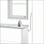
Before you make any tweaks to the OCFD, use the suggested dimensions first and then take your readings. That is, use 4 feet (48 inches) of wire on one side of the block, and then use 1-1/2 feet (18 inches) on the other side of the block. Hang this up like shown in the picture. It doesn't matter if the smaller element is on top, or the longer one is - use whatever position is convenient. You could even tie-wrap it to a long stick, pvc, whatever if you just wanted to stand it up in the corner - however I recommend hanging it.

Remember to run the coax away from this vertical antenna for at least a few feet horizontally for best results.

What I think you might be thinking is that this is somehow "two" antennas - a long one and a short one. Not so. The ENTIRE antenna is critically dependent upon these two lengths - 48 inches one side and 18 inches the other. Trying to tweak the ocfd with other lengths might enhance one band, but totally kill the others. This SINGLE antenna is doing quadruple-duty or more on the various bands - which is convenient, but can also be it's downfall on the higher frequencies - but you have to build it as recommended first.

So cut new lengths as recommended (48 inches and 18 inches) and check out your results - write them down somewhere. Maybe move the antenna if you can to different areas - outside, different walls, etc.

Now you have a reference to compare other antennas to, such as a 5/8 wave - BUT the 5/8 wave vertical is an entirely different antenna than the OCFD, and will be made differently - no tv-type 300:75 ohm transformer etc.

The trap not to fall into is optimizing an antenna before building the "official" one, and getting your own reference. That way you can see how well (or badly) your improvements/modifications work compared to the standard one.
 
Last edited by a moderator:
Status
Not open for further replies.
Top