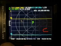
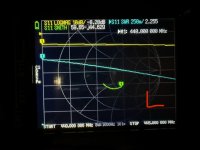
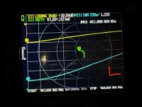
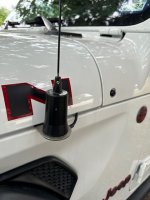
Just installed, antenna mount shows continuity to ground. Coax tests good. 2 different antennas used. Pics with the red C is a Comet 2x4SR, red L is a Larsen NMO270. This almost looks like a tuning issue but the smith chart/low ohms readings are throwing me off.

-
To anyone looking to acquire commercial radio programming software:
Please do not make requests for copies of radio programming software which is sold (or was sold) by the manufacturer for any monetary value. All requests will be deleted and a forum infraction issued. Making a request such as this is attempting to engage in software piracy and this forum cannot be involved or associated with this activity. The same goes for any private transaction via Private Message. Even if you attempt to engage in this activity in PM's we will still enforce the forum rules. Your PM's are not private and the administration has the right to read them if there's a hint to criminal activity.
If you are having trouble legally obtaining software please state so. We do not want any hurt feelings when your vague post is mistaken for a free request. It is YOUR responsibility to properly word your request.
To obtain Motorola software see the Sticky in the Motorola forum.
The various other vendors often permit their dealers to sell the software online (i.e., Kenwood). Please use Google or some other search engine to find a dealer that sells the software. Typically each series or individual radio requires its own software package. Often the Kenwood software is less than $100 so don't be a cheapskate; just purchase it.
For M/A Com/Harris/GE, etc: there are two software packages that program all current and past radios. One package is for conventional programming and the other for trunked programming. The trunked package is in upwards of $2,500. The conventional package is more reasonable though is still several hundred dollars. The benefit is you do not need multiple versions for each radio (unlike Motorola).
This is a large and very visible forum. We cannot jeopardize the ability to provide the RadioReference services by allowing this activity to occur. Please respect this.
You are using an out of date browser. It may not display this or other websites correctly.
You should upgrade or use an alternative browser.
You should upgrade or use an alternative browser.
Jeep Gladiator: Trunk lip NMO mount on hood, wonky VNA readings. Can anyone help me understand what I’m seeing?
- Thread starter OhSixTJ
- Start date
mmckenna
I ♥ Ø
Some matching coils are DC grounded. I'm pretty sure the Larsen 5/8th's wave coil is. Not sure what they use on the NMO-2/70. Take the antenna off and check with a multimeter on the bottom of the antenna coil.
Some matching coils are DC grounded. I'm pretty sure the Larsen 5/8th's wave coil is. Not sure what they use on the NMO-2/70. Take the antenna off and check with a multimeter on the bottom of the antenna coil.
I meant Larsen NMO2/70B, not sure if that matters.
anyways, I’m not sure what you mean to check the bottom of the antenna coil to check for DC grounding. How would I do that?
mmckenna
I ♥ Ø
I meant Larsen NMO2/70B, not sure if that matters.
It probably doesn't.
anyways, I’m not sure what you mean to check the bottom of the antenna coil to check for DC grounding. How would I do that?
Turn the antenna over. You'll see the center tab and the outer brass ring. Check for continuity between those two. Some of the coils are normally DC grounded and you'll get continuity between the outer ring and the center tab.
Got it. I’ll check that after work.Turn the antenna over. You'll see the center tab and the outer brass ring. Check for continuity between those two. Some of the coils are normally DC grounded and you'll get continuity between the outer ring and the center tab.
prcguy
Member
This morning I checked my NMO trunk lip mount in the same spot as the OP with a Larsen NMO 2/70, a 1/4 wave UHF whip and a Comet 2X4SR. All antennas have very useable VSWR across their rated frequency ranges. The OP has a stock setup where I have added wide aluminum tape under a plastic cowl piece which extends the ground plane under the antenna a bit. Not sure if that is why mine is showing better or if there is actually something wrong with the OPs mount, coax or connector.
Larsen NMO2/70 on 2m and 440 amateur


Tram 1/4 wave UHF whip

Comet 2X4SR


Mount location on my Jeep JT

You can see the VSWR is under 2:1 over an impressive frequency range on all antennas.
Larsen NMO2/70 on 2m and 440 amateur
Tram 1/4 wave UHF whip
Comet 2X4SR
Mount location on my Jeep JT
You can see the VSWR is under 2:1 over an impressive frequency range on all antennas.
Attachments
Last edited:
prcguy
Member
This is what I did on the under side of the curved plastic cowl pieces. The tape makes contact with ground where the screws hold it down.@prcguy i think I’m gonna add the foil tape first then test and if I still don’t see anything better then I’ll redo my connector to see what happens.

prcguy
Member
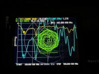
Run a wide S11 VSWR only plot like 100-200MHz on VHF and at least 400MHz to 500MHz on UHF. Or just sweep 100MHz to 500MHz for both VHF and UHF. That will show if the antenna has a good match somewhere meaning the resonant point could be shifted up due to lack of ground plane. Bad coax or connector would usually not show a good resonant point and will be high everywhere or could show reoccurring good and bad points.Thanks for the pic.
I’m also thinking maybe I bent/kinked the coax as I was pulling it through the firewall. From what I’m reading that can have a noticeable impact on SWR.
Run a wide S11 VSWR only plot like 100-200MHz on VHF and at least 400MHz to 500MHz on UHF. Or just sweep 100MHz to 500MHz for both VHF and UHF. That will show if the antenna has a good match somewhere meaning the resonant point could be shifted up due to lack of ground plane. Bad coax or connector would usually not show a good resonant point and will be high everywhere or could show reoccurring good and bad points.
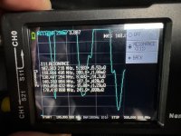
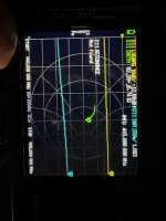
Calibrated and swept 100 to 500. Made sure the mount has ground/bond. Applied the foil. I think either the cable is bad or my connector is bad.
Attachments
prcguy
Member
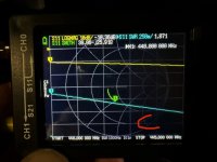
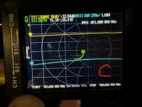
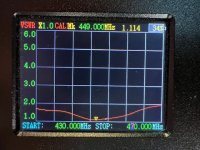
Ooh, what a mess. Do the measurement again but only with the S11 VSWR traces showing, ditch the smith chart and other stuff. In other words turn off all traces except the light blue one. Then put a curser on 146MHz and 445MHz for the Larsen 270 to see where its resonating. If its got a good match just slightly out of band and higher in frequency, that could be lack of a ground plane. Many antennas will go a little high in frequency if the ground plane is inadequate.Calibrated and swept 100 to 500. Made sure the mount has ground/bond. Applied the foil. I think either the cable is bad or my connector is bad.
Your setup should be identical to mine and most antennas I put on my hood mount have a good VSWR and they radiate just fine. You might disconnect the coax connector from the radio and check the ground side of the connector to chassis ground to see if the set screws in the mount are digging through the paint. Otherwise I would have to see the setup to diagnose, which sounds like a long drive for somebody.
prcguy
Member
There is one small difference between our installs, I put several ferrite beads on my coax as it exits the mount, which chokes off RF riding on the coax. Three to four 43 mix or Laird 28 mix ferrite snap on beads are very good at VHF/UHF giving about 20dB of isolation. If your readings were changing when you move your meter around or move your hand up and down the coax the ferrite chokes would calm that down. If your readings are stable then it probably won't do much.

The ohms look funny to me. The screws dig through the paint but something is keeping the hood from grounding/bounding. I added a strap though to provide ground to the mount.
I’ve done a whole lot of NMO installs, never had this issue. That’s why I suspect the mount/cable.
I’ve done a whole lot of NMO installs, never had this issue. That’s why I suspect the mount/cable.
Attachments
prcguy
Member
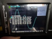
I would not worry about how many ohms at what frequency right now, just see what the frequencies of the low VSWR dips are and what the VSWR actually is there. If this is the Larsen 2/70 it should have a dip with good match around 146MHz then somewhere in the 440-450 range. It could be it has a good match at 149MHz and 452Mhz and that would be good to know if the antenna is actually performing ok somewhere close to where its supposed to be. In that case it could be the ground plane causing the resonant points to move a little out of band.The ohms look funny to me. The screws dig through the paint but something is keeping the hood from grounding/bounding. I added a strap though to provide ground to the mount.
I’ve done a whole lot of NMO installs, never had this issue. That’s why I suspect the mount/cable.
I would not worry about how many ohms at what frequency right now, just see what the frequencies of the low VSWR dips are and what the VSWR actually is there. If this is the Larsen 2/70 it should have a dip with good match around 146MHz then somewhere in the 440-450 range. It could be it has a good match at 149MHz and 452Mhz and that would be good to know if the antenna is actually performing ok somewhere close to where its supposed to be. In that case it could be the ground plane causing the resonant points to move a little out of band.
Yeah it’s way better at 149, I don’t remember what it was in the UHF side.
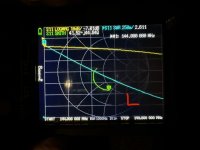
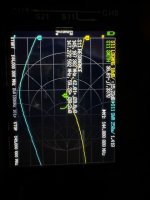
I don’t understand how it could be a ground plane issue when it had way better SWR with way less ground plane in its previous spot. I ordered a new mount in case this one was faulty or I messed it up some how.
My previous install location and SWR
Attachments
prcguy
Member
There may be more ground plane or capacitance from the whip to ground plane in the old location, but that doesn't mean it worked better than top of the hood. Get an Allen wrench and lift the whip out as far as it will go, that will lower the freq and hopefully center it around 146MHz.Yeah it’s way better at 149, I don’t remember what it was in the UHF side.
I don’t understand how it could be a ground plane issue when it had way better SWR with way less ground plane in its previous spot. I ordered a new mount in case this one was faulty or I messed it up some how.
My previous install location and SWR
prcguy
Member
I would be very surprised if the hood is insulated from the rest of the vehicle and an ohmmeter will tell you that. Even if it was insulated there is plenty of ground plane with a lip mount for a UHF and the VSWR should be acceptable. If the hood turns out to be insulated on purpose then the lip mount is probably not a good idea. My Mojave hood is steel and grounded through hinges and other things.I completely forgot about galvanic corrosion. My rubicon’s hood is aluminum. Bonding it to the rest of the jeep (and the set screws digging into the paint) might not be a good idea.
Looks like I’m going back to my fender mount for now.
I would be very surprised if the hood is insulated from the rest of the vehicle and an ohmmeter will tell you that. Even if it was insulated there is plenty of ground plane with a lip mount for a UHF and the VSWR should be acceptable. If the hood turns out to be insulated on purpose then the lip mount is probably not a good idea. My Mojave hood is steel and grounded through hinges and other things.
I could not get a tone when probing the hood against a good ground. I think there’s something between the steel hinge and the aluminum hood to prevent galvanic corrosion. Ford has a bulletin out warning against bonding their aluminum panels to avoid corrosion, I’m betting Jeep would recommend against it too.