• To anyone looking to acquire commercial radio programming software:

    Please do not make requests for copies of radio programming software which is sold (or was sold) by the manufacturer for any monetary value. All requests will be deleted and a forum infraction issued. Making a request such as this is attempting to engage in software piracy and this forum cannot be involved or associated with this activity. The same goes for any private transaction via Private Message. Even if you attempt to engage in this activity in PM's we will still enforce the forum rules. Your PM's are not private and the administration has the right to read them if there's a hint to criminal activity.

    If you are having trouble legally obtaining software please state so. We do not want any hurt feelings when your vague post is mistaken for a free request. It is YOUR responsibility to properly word your request.

    To obtain Motorola software see the Sticky in the Motorola forum.

    The various other vendors often permit their dealers to sell the software online (i.e., Kenwood). Please use Google or some other search engine to find a dealer that sells the software. Typically each series or individual radio requires its own software package. Often the Kenwood software is less than $100 so don't be a cheapskate; just purchase it.

    For M/A Com/Harris/GE, etc: there are two software packages that program all current and past radios. One package is for conventional programming and the other for trunked programming. The trunked package is in upwards of $2,500. The conventional package is more reasonable though is still several hundred dollars. The benefit is you do not need multiple versions for each radio (unlike Motorola).

    This is a large and very visible forum. We cannot jeopardize the ability to provide the RadioReference services by allowing this activity to occur. Please respect this.

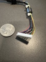
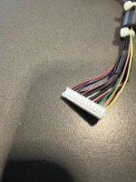
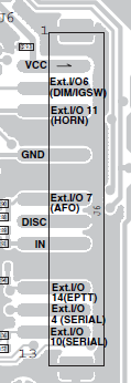
OPC-1939 connector (PCB side)

KD2DES

Member
Premium Subscriber
Joined
Nov 12, 2023
Messages
23
Location
New York, NY
Does anyone know the connector name of the OPC-1939 and can I find it at Mouser? Thank you.
 

Attachments

  • IMG_9194.jpeg
    IMG_9194.jpeg
    116.7 KB · Views: 2
  • IMG_9192.jpeg
    IMG_9192.jpeg
    99.8 KB · Views: 2

Teotwaki

Member
Joined
Aug 3, 2008
Messages
423
Location
SoCal
Hi! Did you ever find a good source for those 13 pin JST connectors? What is the pin spacing?
 

KD2DES

Member
Premium Subscriber
Joined
Nov 12, 2023
Messages
23
Location
New York, NY
Hi! Did you ever find a good source for those 13 pin JST connectors? What is the pin spacing?
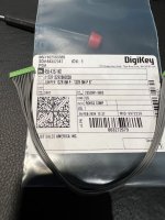
Man, what a coincidence... I got TODAY a connector from DigiKey, it was back-ordered. The ones I had gotten before all were too thin, but this one that arrived today is the one. It's JST's 13ZR-8M-P. see attached pictures. I got a jumper model, because I could not find a pigtail (tell me if you do). The silly part of all this is that the wires are very thin and I don't know how am I going to solder them on a connector. They are also all the same color!
IMG_9867.jpeg

IMG_9868.jpeg
 

Teotwaki

Member
Joined
Aug 3, 2008
Messages
423
Location
SoCal
The attached doc has the pinout for that JST connector so the wire color won't matter, just count the pins carefully. I would cut the jumper cable roughly in half, strip the ends of only the wires you need: Audio out , Ground , Audio In , PTT

I would first solder those four to a small PCB such as the ones in this Elegoo kit on Amazon

ELEGOO 32 Pcs Double Sided PCB Board Prototype Kit for DIY Soldering with 5 Sizes Compatible with Arduino Kits

https://m.media-amazon.com/images/I/91MBDISdwhL._SL1500_.jpg

Then you can run out the heavier external wires to whatever connector you will plug into your radio. Be sure to have some sort of strain relief so that the external wires can't be tugged at. If you can't find a way to fasten down the little PCB board somewhere inside the radio, wrap it in electrical tape after you finish testing.

On the heavier wires you should add some Ferrite beads to choke off any RF that might get coupled in.
 

Attachments

  • OPC-1939 Cable.pdf
    248.8 KB · Views: 5

Teotwaki

Member
Joined
Aug 3, 2008
Messages
423
Location
SoCal
Forgot to say I think getting the jumper model was a good choice as when you cut it in half you can now make two different interface cables to play with. Thanks for sharing your research!!!


Teotwaki

Member
Joined
Aug 3, 2008
Messages
423
Location
SoCal
From the ICOM service manual for the F5021 the pinout looks like this on the top side of the PCB

Screenshot 2024-02-20 194412.png
 

Teotwaki

Member
Joined
Aug 3, 2008
Messages
423
Location
SoCal
KD2DES -

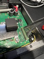
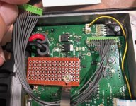
Thanks again for the pointer on the connector for J6! I have received mine and wanted to share how I will interface it to the outside world. I made up a little board to tie down the wires from the connector and then terminate a CAT5 cable to RJ45 connector. The RJ45 will plug into a Signalink USB box.

Next I'll be cutting the gray wires and soldering them to the board in numeric order. The CAT5 cable will be routed thru the rubber block holding the power leads and I'll place ty-wraps on either side to anchor the cable.

Note on Page 1 in the data sheet for the OPC -1939 accessory they mention that certain solder pads can be used to affect audio paths, audio levels and also the sense of the PTT line.

image1(8).jpeg
 

Teotwaki

Member
Joined
Aug 3, 2008
Messages
423
Location
SoCal
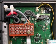
Here is the completed I/O hack. Unfortunately I have to go into the programming s/w and specify that Pin 11 on J6 is to be used for PTT.
I'll need to go borrow the s/w and cable again before I can test with the Signalink
image0(18).jpeg
 

Teotwaki

Member
Joined
Aug 3, 2008
Messages
423
Location
SoCal
I did get my hands on my friend's ICOM software and update Pin 11 for PTT. I conducted some over the air tests with VARA FM on VHF and was able to set audio levels and "ping" other stations.
 
Top