RF switch w/ N connectors for up to 3 GHz

Status
Not open for further replies.

videobruce

Member
Premium Subscriber
Joined
Jan 5, 2004
Messages
412
Location
Buffalo NY
I'm looking for a RF (antenna or coax if you perfer) switch for receive up to 3 GHz. These are the ones I have found in order of cost;

1. Jetstream CO-201N $28, speced to 2 GHz (unknown quality)
2. Daiwa CS-201GII $42, speced between 1 GHz and 2 GHz (??), (appears similar to Jetstream)
3. Diamond CX210N $66, speced to 3 GHZ (clearly has the best specs)
4. Alpha Delta 2B/N $68, speced to 1.3 GHz, includes lightning protection

I have a older Daiwa/MFJ SO-239 2 position switch and it does have a center off position. I was told the Jetstream doesn't. Unknown about the current Daiwa.
I like the built in lightning protection with the Alpha Delta, but the bandwidth is only speced to 1.3 GHZ.
The Diamond clearly has the best specs, but no lightning protection.
Unknown how similar the Jetstream and the Daiwa switches are. Frequency specs for the Daiwa are inconsistant. Some only go up to 1 GHZ, others go to 2 GHz.

Has anyone scoped any of these switches regarding losses at higher frequencies??
 
Last edited:

prcguy

Member
Joined
Jun 30, 2006
Messages
15,391
Location
So Cal - Richardson, TX - Tewksbury, MA
Check Epay for surplus microwave switches from Dow Key, Teledyne, Transco, Loral, Sector Microwave and others.I have purchased some very expensive NOS switches, RF relays and transfer switches and some good to 18GHz for less than $20.
prcguy
 

trooperdude

Member
Database Admin
Joined
Nov 25, 2003
Messages
1,506
Location
SFO Bay Area and Las Vegas NV
Check Epay for surplus microwave switches from Dow Key, Teledyne, Transco, Loral, Sector Microwave and others.I have purchased some very expensive NOS switches, RF relays and transfer switches and some good to 18GHz for less than $20.
prcguy

+1

There are some really good deals out there on surplus commercial gear.


I don't think I've paid over $20 for any piece of >$200 commercial gear on FleaBay.
 

videobruce

Member
Premium Subscriber
Joined
Jan 5, 2004
Messages
412
Location
Buffalo NY
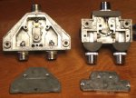
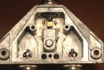
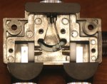
Here are screen shots of the Diawa/MFJ 2 position switch (w/ SO-239), the Diawa version and the Diamond. Notice the different setup between the two. The Diamond has one copper strip, the Diawa has two.

Major disadvantages of the Diamond are:
the unused port is NOT grounded,
there is no center 'off' (grounded) position,
more expensive than the Diawa.

BUT, specs tell a different story. The Diamond is speced up to 3 GHz which brings the question; why is this design better than the older Diawa?
The other question for both, if you look close at the point of actual contact, the surface area is pratically nill. One would think that that wouldn't be able much more than a few watts and the transfer of signal (either way) would be questionable.

Any RF engineers out there have any comments?
 

Attachments

  • Diawa-Diamond switches.jpg
    Diawa-Diamond switches.jpg
    123.7 KB · Views: 3,579
  • Diawa-MFJ switch.jpg
    Diawa-MFJ switch.jpg
    113.3 KB · Views: 2,783
  • Diamond switch.jpg
    Diamond switch.jpg
    112.5 KB · Views: 2,523
Last edited:

Scott_PHX_APP

Member
Joined
Sep 3, 2003
Messages
131
Location
Phoenix AZ, Gilbert
I'm confused as to which is which, but that aside, the last picture looks like it provides a better contant impedance looking at the spacers and cavity, but as you mentioned, the contact area is a bit... That to me would only limit the power handeling but I'm not an RF engineer either... :) (After reading again, and again, I see the Diamond is the last picture) :D My bad... Anyway, that's my $.02 worth.
Later...
 

videobruce

Member
Premium Subscriber
Joined
Jan 5, 2004
Messages
412
Location
Buffalo NY
I corrected the text.
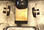
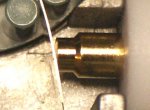
The closeup of the Diamong is a little deceiving. The point of contact is very little. The edge of the round flat pin is the only part that touches the copper blade.

See if these closeups help.
 

Attachments

  • Diawa-MFJ switch points.JPG
    Diawa-MFJ switch points.JPG
    85.1 KB · Views: 1,856
  • Diamond switch points.JPG
    Diamond switch points.JPG
    60.1 KB · Views: 1,706
Last edited:

Scott_PHX_APP

Member
Joined
Sep 3, 2003
Messages
131
Location
Phoenix AZ, Gilbert
Great close-ups! My comments from before still stand in that the one on the left above would have better impedance characteristics do to the better internal components layout, etc. As to the contact surface, I agree that it's not much, but as I mentioned before, I think that would have more of an effect on the power rating and in the receive mode, that wouldn't matter... BTW, is that one on the left in the normal handle position for that contact? If it moves a bit more, and for that matter WHEN it moves to the closed position, you get a slight wiping action.
Later...
 
Last edited:

Mike_G_D

Member
Joined
Dec 19, 2002
Messages
1,241
Location
Vista, CA
switch switch, oh which switch is which to switch with?

I agree with the last post (by Scott_PHX_APP). I have an RF background and can see from the pictures that the Diamond looks like a better constant impedance than the Daiwa over a wider frequency range. Of course you would really need to put these on a good calibrated network analyzer and do a frequency vs. S-Parameter sweep to fully characterize them.

That being said, I have a Daiwa CS-201 - I think a pretty old one - and I can confirm that the "wiper action" does seem to come into play. As it got older and having been used a lot I definitely noticed that the switch became touchy and had to play with it a bit to get the best connection. It was a problem as it would seem to switch firmly but I would notice degradation in reception which I could alleviate if I rapidly switched it back an forth for a bit. Of course that made me nervous of using it for transmission!

Your pictures are great and make me wonder if I can get the switch back to speed now by opening it up and cleaning the contacts. I may try that. The SO-239 connectors also limit the effective bandwidth. I am surprised that the Diamond specs to 3GHz with SO-239 connectors! I wouldn't want to use SO-239 above even 300MHz, myself. I much prefer N connectors.

As to the power handling - I am sure the switches were characterized for that and the apparent contact area for the center conductor is only part of the story. The whole switch with the tuned internal cavities form the "outer conductor/shield" and carry a large part of the power handling load.

Again, great pictures - very nice closeups!

-Mike
 

videobruce

Member
Premium Subscriber
Joined
Jan 5, 2004
Messages
412
Location
Buffalo NY
Sorry that the order of the two switches wasn't clear. The Diawa is on the left (in the center off position), the Diamond is on the right (I should of taken another shot of it in a closed position).
I snapped a few shots of each switch so as to use the best focused one.
The Diamond does have N connectors, the older Diawa only has SO-239.

I will be running a sweep test on these as soon as I get the cables made up. I just started to use N connectors, graduating up from the outdated PL-259's. :wink:
 
Last edited:

videobruce

Member
Premium Subscriber
Joined
Jan 5, 2004
Messages
412
Location
Buffalo NY
Working with N connectors

Slightly OT but, regarding working with N connectors; I am looking for the best performance up to 3 GHZ as possible. I'm testing these cables with a Spectrum Analyzer that has a tracking generator. What I have found so far is way less than ideal. It's amazing what this device revels about a simple patch cable. What appears to be a good fitting isn't.

Questions;
1. To test just a patch cable (nothing else), when useing the TG, can I assume I do not do a 'Normalize' routine, since that would only 'flatten' out the trace making any cable look good?
2. Using smaller 50 ohm cables for jumpers, how much of a difference will various types of shielding make regarding loss and flatness? I see ther is a great difference between RG-58 and the newer LMR-195 (same diameter) regarding loss (and price).
3. How much of a difference between a N connector designed for RG8/LMR400 with a 'reducer' (same as one for a PL259) and a N connector designed for a RG58/LMR-195 cable with no reducer have at frequencies above 1 GHz?

The reasons for the questions are, with the few different type of N connectors I have tried so far, I have seen a difference between connectors and the different types of RG58 cables I have. I'm not sure if it is improper instalation on my part (stripping, soldering etc.), or the actual connector and/or cable.

Input?
 

zz0468

QRT
Banned
Joined
Feb 6, 2007
Messages
6,034
Slightly OT but, regarding working with N connectors; I am looking for the best performance up to 3 GHZ as possible. I'm testing these cables with a Spectrum Analyzer that has a tracking generator. What I have found so far is way less than ideal. It's amazing what this device revels about a simple patch cable. What appears to be a good fitting isn't.

In an ideal world, you would be using a network analyzer for this. The tracking generator is only telling you part of the story, although a very useful part.

Questions;
1. To test just a patch cable (nothing else), when useing the TG, can I assume I do not do a 'Normalize' routine, since that would only 'flatten' out the trace making any cable look good?

Fabricate, or otherwise obtain, the necessary cables and adapters to loop the TG back to the analyzer, and then 'normalize' that setup. Then, insert the cable under test, and any impairments you see should be those in the cable or device being tested. You are correct in assuming that if you normalize the entire test setup, you would be correcting out any anomalies.

2. Using smaller 50 ohm cables for jumpers, how much of a difference will various types of shielding make regarding loss and flatness? I see ther is a great difference between RG-58 and the newer LMR-195 (same diameter) regarding loss (and price).

It makes a BIG difference. If you can normalize some of the impairments out, you can live with it, but that's not always practical, nor desirable. You should invest in some very high quality cables for use with your TG and analyzer. It can go only so far in making a lousy cable look normal for test purposes, and a bad cable can introduce errors in other points in the network, so you're better off using good cables to start with. Goretex cables are sometimes available on eBay for a fraction of their original cost. Wanna buy 'em new? The 1 meter cables on my HP8722 network analyzer cost about $3500 apiece new.

3. How much of a difference between a N connector designed for RG8/LMR400 with a 'reducer' (same as one for a PL259) and a N connector designed for a RG58/LMR-195 cable with no reducer have at frequencies above 1 GHz?

The higher the frequency, the more critical it is to use the proper connector on the proper cable. Is there actually such a reducer for the RG8/LMT400 connector to adapt it to smaller cable? I've never seen such a thing. I just order the proper connector to start with. The N connector is designed to maintain the characteristic impedance of the cable across the connectors. Anything that alters the geometry of the cable and/or connector will alter the characteristic impedance at that point, and the higher in frequency you go, the more of a detrimental impact it will have. A GOOD quality N connector, properly installed on GOOD cable is usable beyond 18 GHz.

The reasons for the questions are, with the few different type of N connectors I have tried so far, I have seen a difference between connectors and the different types of RG58 cables I have. I'm not sure if it is improper instalation on my part (stripping, soldering etc.), or the actual connector and/or cable.

It could be all of the above. First, RG-58 is lousy cable above a few hundred MHz. I use it for jumpers at 800 in cases where it doesn't matter, say, a couple of feet from a radio to a service monitor, when I just need to couple signal across. But if losses and stability are important, I use RG-142 at a minimum, Maybe RG-214 at higher power levels, and Goretex into the microwave region.

Quality of installation on the connectors plays an important part, too. Get yourself a directional coupler, if you don't already have one, and sweep your cables for return loss and see the variation from one cable to another.

There's a damn good reason why Gore, HP, and Wiltron charge so much for their phase stabalized cables.
 
Last edited:

videobruce

Member
Premium Subscriber
Joined
Jan 5, 2004
Messages
412
Location
Buffalo NY
In an ideal world, you would be using a network analyzer for this
Other than cost and complexibility, what is the difference between a SA w/ a TG and a NA (w/ a TG)??
Fabricate, or otherwise obtain, the necessary cables and adapters to loop the TG back to the analyzer
That's what the patch cables I was making were for.
Is there actually such a reducer for the RG8/LMT400 connector to adapt it to smaller cable? I've never seen such a thing.
A U175 (or is it 174) reducer, the same that is used with a PL259 connector. Never working with N before, I didn't know this either.
Get yourself a directional coupler
It's on my list, but prices for new are a little much. I have been looking on e-bay, but missed out on a couple.
First, RG-58 is lousy cable above a few hundred MHz.
Even for jumpers less than two feet long?
phase stabalized cables
Almost sounds as slaes talk for a high end audio cable. :wink:
 

zz0468

QRT
Banned
Joined
Feb 6, 2007
Messages
6,034
Other than cost and complexibility, what is the difference between a SA w/ a TG and a NA (w/ a TG)??

A spectrum analyzer with a tracking generator and directional coupler is essentially a scalar network analyzer. You get frequency and amplitude information. A vector network analyzer gives you phase information as well.

That's what the patch cables I was making were for.

If you're having difficulty fabricating cables of sufficient quality, you may want to consider just buying some ready made. Get some GOOD cables, then use those with your instrument to teach yourself to MAKE good cables. At 3 GHz, putting the connectors on right is critical. And you WILL see errors on the analyzer.

A U175 (or is it 174) reducer, the same that is used with a PL259 connector. Never working with N before, I didn't know this either.

I've never seen an 'N' connector that uses a PL-259 type reducer. This doesn't sound right.

It's on my list, but prices for new are a little much. I have been looking on e-bay, but missed out on a couple

Keep trying. They're out there, and will make your SA/TG combo a whole lot more useful.

Even for jumpers less than two feet long?

Yep. Especially for a piece of test gear that sweeps over a wide frequency range.

Almost sounds as slaes talk for a high end audio cable. :wink:

Almost. But they're for real. Look 'em up on eBay or Google. I have some rated to 40 GHz. If I attempt a measurement at that frequency with lesser cables, the results are completely useless. At 3 GHz, it's not a big deal, but at some point, a coax stops acting like coax and goes into propagation modes like waveguide. So, between that, increasing loss with higher frequencies, and the need for phase stability when using a vector network analyzer, the use of high end cable for test jumpers gets pretty important.

In your case, RG-142 jumpers, professionally made and swept, will suffice. I don't remember from your previous posts... is this device a toy, or a tool? If you're earning a living from it, you want the best you can get.
 

videobruce

Member
Premium Subscriber
Joined
Jan 5, 2004
Messages
412
Location
Buffalo NY
you may want to consider just buying some ready made
I have considered that, depending on cost.
At 3 GHz, putting the connectors on right is critical. And you WILL see errors on the analyzer.
I have found this out. :(
I've never seen an 'N' connector that uses a PL-259 type reducer. This doesn't sound right.
Neither did I or heard of it. I assumed those reducers were only for PL259's. R&L Electronics was the one who told me about these. Those reducers screw into the N connector they sell just as they do with a PL259. It was fairly easy (compared to those multipart fittings which I hate).
at some point, a coax stops acting like coax and goes into propagation modes like waveguide.
Without getting too far OT, I partially understand waveguide, but could you expand on that topic? Around what frequency does this happen? I suppose there is a formula for this?
is this device a toy, or a tool?
If you mean the source, they would be receivers and antennas. Namely WiFi for above 1 GHz and 2-way radio below.
 

zz0468

QRT
Banned
Joined
Feb 6, 2007
Messages
6,034
I have considered that, depending on cost.I have found this out. :(

Sometimes being cheap is counter productive. You don't always have to buy new, but as you go higher in frequency, you can't scrimp in quality.

Neither did I or heard of it. I assumed those reducers were only for PL259's. R&L Electronics was the one who told me about these. Those reducers screw into the N connector they sell just as they do with a PL259. It was fairly easy (compared to those multipart fittings which I hate).

Do those connectors have a frequency rating? Not all N connectors are created equal. What's cheap and easy to put on does not equate to proper performance at 3 GHz. I've seen some N connectors that are just fine at 6 GHz, but much higher, and they cause all manner of problems. Still other N connectors are just fine up past 24 GHz. Cheap connectors might not maintain the characteristic impedance of the coax at higher frequencies.

Without getting too far OT, I partially understand waveguide, but could you expand on that topic? Around what frequency does this happen? I suppose there is a formula for this?

It's an extremely complex subject, beyond the scope of this thread. Suffice it to say, when the wavelength of the signal approaches the dimensions of the coax, the cable ceases to function as coax. At 3 GHz, it's not much of a worry for you. At 5.8 GHz, it might be. Just as an example, at 5.8 GHz, 1/2 inch cable is perfectly usable. The larger, lower loss 7/8 inch cable is not.

If you mean the source, they would be receivers and antennas. Namely WiFi for above 1 GHz and 2-way radio below.

What I meant was, are you earning a living from this device, or is it a toy in your ham shack? If it's to earn a living, suck it up, pay the money, and get the high quality components you need.
 

videobruce

Member
Premium Subscriber
Joined
Jan 5, 2004
Messages
412
Location
Buffalo NY
Sometimes being cheap is counter productive.
IOW's you get what you pay for. I wasn't implying that I wanted the cheapest, I just wasn't going to spend big bucks on any of this (other than the SA which I went well above what I wanted to spend).
Do those connectors have a frequency rating?
Not that I know of.
are you earning a living from this device, or is it a toy in your ham shack?
Really hate to call it a toy, but I'm not earning a living from it. :wink:
when the wavelength of the signal approaches the dimensions of the coax, the cable ceases to function as coax.
Then what happens?
at 5.8 GHz, 1/2 inch cable is perfectly usable. The larger, lower loss 7/8 inch cable is not.
Funny you mention that as I just read specs from cables from this company;
http://www.shireeninc.com/wp-content/uploads/shireen-RF-cables-specs.pdf

and noticed the larger cables had a lower cut off frequency and couldn't understand that since larger cables have lower losses at higher frequencies than smaller diameter cables.
 

zz0468

QRT
Banned
Joined
Feb 6, 2007
Messages
6,034
IOW's you get what you pay for. I wasn't implying that I wanted the cheapest, I just wasn't going to spend big bucks on any of this (other than the SA which I went well above what I wanted to spend).

In other words... yes. You get what you pay for. Scrimping on cables detracts from the accuracy and utility of your test equipment.

Not that I know of.

Then don't use them for test cables until you understand their limitations. They may be great to 1000 MHz, or for your ham rigs, and a big impedance bump on the line above that.

Really hate to call it a toy, but I'm not earning a living from it.

That's ok... it's a toy! Believe me, I understand. My toy room is better equipped than any commercial or gov't shop I've ever worked in. I take toys SERIOUSLY!

Then what happens?

The signal changes propagation modes as you go up in frequency. If you were to sweep it, from DC to it's cutoff point, you would see the loss gradually rise as the frequency goes up. Then all of a sudden, the slight slope on your sweep would develop lots of ripples where the loss might swing 40 to 60 db or more. That's the point where it stops behaving like coaxial cable, and waveguide propagation modes take over.

Funny you mention that as I just read specs from cables from this company;
http://www.shireeninc.com/wp-content/uploads/shireen-RF-cables-specs.pdf

and noticed the larger cables had a lower cut off frequency and couldn't understand that since larger cables have lower losses at higher frequencies than smaller diameter cables.

And now you know why.
 

videobruce

Member
Premium Subscriber
Joined
Jan 5, 2004
Messages
412
Location
Buffalo NY
The signal changes propagation modes as you go up in frequency. If you were to sweep it, from DC to it's cutoff point, you would see the loss gradually rise as the frequency goes up. Then all of a sudden, the slight slope on your sweep would develop lots of ripples
Something like this;
Note; scope is set to 2db per div. not 10db. This is a 2 foot BNC to BNC 8259 cable.
 

Attachments

  • BNC_8259.jpg
    BNC_8259.jpg
    48.7 KB · Views: 1,617

zz0468

QRT
Banned
Joined
Feb 6, 2007
Messages
6,034
Yeah, kind of along those lines, but make those amplitude excursions more like 40 db, not 2 db.

That's a pretty crappy looking cable, by the way. =)
 

videobruce

Member
Premium Subscriber
Joined
Jan 5, 2004
Messages
412
Location
Buffalo NY
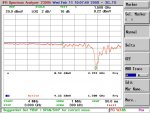
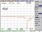
Finally, here are screen shots of the Delta2-BN switch.
Please take note that the vertical divisions are set to 2db, not the standard 10db.

This has great response up to 1.5 GHz (specs list up to 1.3 GHz) and useable response up to 2.2 GHz. Above that it falls apart with a major 'dip' around 2.35 GHz.

Anyone want to comment about this?
 

Attachments

  • DELTA2.JPG
    DELTA2.JPG
    79.7 KB · Views: 1,452
  • DELTASWT.JPG
    DELTASWT.JPG
    83.9 KB · Views: 1,441
Status
Not open for further replies.
Top