1/4, 1/2, Full Wave How Do i Decide?

Status
Not open for further replies.

squelchON

Member
Joined
May 25, 2010
Messages
2
Location
Maine
I'm a communications guy in the Army and i was hoping some of you experienced radio guys can help me. I've googled my question and found some similar questions here on this site but i'm trying to get a little more specific answer.

I have a really good old manual i found on making field expedient antennas. It has long-wire, half-rhombic, all kinds. The problem is that for each different type of antenna, it gives the formula for figuring out element lengths for 1/4, 1/2, and 1 (Full) Wave, but it never specifies which should be used with the different types of antennas or which should be used depending on what type of radio it is being connected to. This is all emergency field expedient stuff so i'm not talking about having antenna tuners, or other types of equipment. I'm talking about i'm in the middle of no-where and i need to make an antenna for my radio.

I'm Utilizing VHF-Lo FM(SINCGARS), VHF-Hi AM, and HF AM(SSB, USB, ALE) radios.

I want to make this standardized training for me and my guys, but i want to know what i'm talking about before i put it into action. Any help you guys can give me would be greatly appreciated, thanks.
 

benbenrf

Member
Joined
Mar 27, 2009
Messages
287
Location
United Kingdom
Lets start with the Half Rhombic ........ and these notes are from an old US Army Field Manual.

HALF ROHMBIC
* 200 feet of WD-1/TT or WD-1A/TT (wire/cable)
* Electrical Tape
* 400-600 ohms terminating resistor
* Insulators or material to construct field expedient insulators
* Radio set
* Knife
* Suspension line
* Measuring device
* Compass
* Signal Operating Instructions (SOI) with frequency and call signs
* Large open area

To erect the antenna follow these steps:

* Determine azimuth from the transmitting radio to the receiving radio.
* Measure 100 feet of wire.
* Bend the wire in half to find the apex point for the connection of the insulator.
* Connect insulator at the apex point and at both ends of the wire.
* Tie a halyard to the insulator at the apex point. Suspend the apex 20 - 30 feet above the ground.
* Separate the two ends of the wire, ensure you keep them on line with the desired transmission azimuth.
* Connect a wire to the ground side of the insulators at both ends of the wire, and stake them to ground.

Install a counterpoise.
o Run a wire from the ground side of the insulators at the ends of the antenna wire.
o (Ensure that the counterpoise wire is directly under the antenna and one foot off the ground.)
o Attach another piece of wire from the near end ground stake to a screw on the radio set case.

For a uni-directional antenna attach a 600 ohm, 1 or 2 watt resistor across the far end insulator. for a bi-directional antenna leave the resistor off.

.. is this the sort of info you are wanting to put together?
 

Alliance01TX

Member
Premium Subscriber
Joined
May 11, 2007
Messages
383
Location
DFW Texas
Antenna - Emergency field expedient

Howdy

Looking at your post and the "Emergency Field Expedient" Antenna request seems to indicate you and the team would be 'on-the-move and based on the load-out you are caring the most obvious would be to use a 1/4 wave on the VHF High / UHF Bands and a 1/2 wave on the lower bands if you have the ability to carry or will this be via Humvee are only a patrol based work? this would add several additional points to the discussions if other than a boots-on-the-ground senerio...

The post prior has a good rite up that discusses the finer points....my line of questions are around the usage and related matters below...

The other factors would be if you were in a fixed Comm's station and or the expected environment, and if you could get the antenna's up high to increase your contact ranges. Desert, Jungle, Hills or mountains might offer some trade offs or complexities,it depends on your assignement...

We have seen SOF Comm Sgt use standard 14 gage house wire to make a SATCOM antenna that reduces the load by 25% estimated, although not perfect it works in a jam and the wire provides multiple options to use to wire for other means (jumping a car battery, snare, etc,,,)

It really gets down to the most common use of and the frequency of likely use of each Radio Band and the other factors discussed above too....

Can you provide more details?

Thx

Bill
 

squelchON

Member
Joined
May 25, 2010
Messages
2
Location
Maine
More Info

Thanks for the replies so far, theres been some good info.

The situation i'm looking at would be a fixed-position antenna. Were not infantry guys, and we don't move locations rapidly. Probably most common terrain would be desert (at least for the immediate future), but we have the chance of operating pretty much in any/all environments. Sorry, I know that doesn't really give you much more specifics. I'm just trying to get my general knowledge down so i know in a particular situation what wave size i'll go with and why. As i talked about earlier, i have a pretty good manual as far as the construction, materials, etc. portion, but its kinda the finer points it leaves out.

What i take away so far is that a general rule, 1/4 wave for my VHF/UHF and 1/2 for my HF. Is this because of 1/4 and 1/2 requires less length for the antenna element and the portability would be better? That would make sense, even if i am in a fixed position, i still may be constrained on how much room i have available to construct an antenna, and wouldn't want or have room for a 400 ft antenna.

Can we discuss more about the counterpoise? I'm aware of it, but still a little fuzy on correctly installing/implementing it and what it does. This is what i think i know. It creates a false ground, and since it is not actually connected to the ground(earth), it pushes the transmission signal out better?

I understand in runs directly on the antenna element and is 1 foot off the ground but as far as the connection:

Close end is connected the radio by a case screw (effectively grounding to the radio?) the far end is attached to an insulator all while running directly under the main antenna element?

Also, when utilizing the counterpoise on the half rhombic, my resistor is attached to the end of the main antenna element, and to the counterpoise?

Sorry for all the additional questions, they really don't teach us what they should about radio propigation, etc. I'm often familiar with terms but are not quite sure what they actually mean or what they do.
 

benbenrf

Member
Joined
Mar 27, 2009
Messages
287
Location
United Kingdom
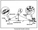
Half rhombic diagram

Attached is a diagram of the HALF RHOMBIC layout principal .... in addition, note the following

- insulators at all 3 ends
- resistors bridging insulators at bottom angles
- connection of counter poise to radio chassis
- counterpoise is connected below the resistors - not above (i.e. counterpoise is isolated from inverted -v antenna wire by resistors)
- radio antenna connection to slanted wire

- Counterpoise serves as an artificial ground [element]
- Tx/Rx is in line with the antenna (not @ 90 deg) and best towards/from end of antenna furthest from radio.
- resistor rated wattage should be 50%, or more, the radio transmitting wattage
- total antenna wire length (excluding counterpoise) - 2 wavelengths or more is best

Hope this all helps..........
 

Attachments

  • RHOMBIC 1.jpg
    RHOMBIC 1.jpg
    45.6 KB · Views: 6,963
Last edited:

prcguy

Member
Premium Subscriber
Joined
Jun 30, 2006
Messages
16,433
Location
So Cal - Richardson, TX - Tewksbury, MA
Nobody mentioned the Vertical Half Rhombic being discussed is designed for the 30-76MHz range at very low power from a PRC-25 or 77. Its also very high impedance at the feed point which the 25 and 77 would partially make up for with their preset internal antenna matching but you would want to use a 4:1 or greater balun with a modern SINCGARS radio.

The Vertical Half Rhombic is also a bit obscure these days and I have never met anyone that actually used one in the military (I have used them on 6m) since they take up way too much real estate for the performance improvement. Its a great antenna for VHF skip or tropo work but the takeoff angle is not consistent or low enough for best point to point terrestrial radio links. I question why it was even mentioned.

I would recommend the OP find a copy of TM 11-666, "Antennas and Radio Propagation" if its still in the military system. This nicely explains most everything he was asking for without getting into boring formulas.

I have an inventory of many current mil HF/VHF/UHF antennas and have probably used most portable types at one time or another, so I'm familiar with what the OP is needing. If I had more spare time I could put together a training course focusing on field expedient antennas for the PRC-138/PRC-150, SINCGARS, MBITR/PRC-152/PRC-117F and other current radios. If the OP can PM me I can probably send some books or info on the subject.

Also, I would avoid the SOF #14 wire dual loop Satcom antenna mentioned in this thread. The guy that designed it doesn't really understand what he cobbled together and at best its much less than 50% of the worst little pocket sized Satcom antenna ever deployed. I've heard some units have left their issued Satcom antenna behind thinking this antenna is good and that could be a fatal mistake. Same goes for the home made MBITR wire antenna that zig-zags inside the back of a vest or pack. its a really bad idea and somehow it propagates through the military circles as a good idea.

The best wearable MBITR antenna I have seen so far is simply remoting the 1m blade antenna high on the body with an extension cable, clip on holder and a dangling counterpoise wire. I put together some prototypes and shipped them to guys in Iraq and Afghanistan long ago and eventually several companies started producing versions but they left out the counterpoise wire and lost some performance.

I should probably stop now, otherwise I could rant all day long about the goofy things I've seen done with military antennas.
prcguy


Attached is a diagram of the HALF RHOMBIC layout principal .... in addition, note the following

- insulators at all 3 ends
- resistors bridging insulators at bottom angles
- connection of counter poise to radio chassis
- counterpoise is connected below the resistors - not above (i.e. counterpoise is isolated from inverted -v antenna wire by resistors)
- radio antenna connection to slanted wire

- Counterpoise serves as an artificial ground [element]
- Tx/Rx is in line with the antenna (not @ 90 deg) and best towards/from end of antenna furthest from radio.
- resistor rated wattage should be 50%, or more, the radio transmitting wattage
- total antenna wire length (excluding counterpoise) - 2 wavelengths or more is best

Hope this all helps..........
 
Status
Not open for further replies.
Top