
soundchaser
Member
Inspired by this post http://forums.radioreference.com/build-your-own-antenna/109144-4-bay-vhf-dipole-array-project.html
I decided to try making this style of antenna for 800 MHz DTRS monitoring. The results exceeded my expectations.
I live in a mountainous area, and 800 MHz signals are difficult to receive. I am currently using a Yagi, but that limits me to one direction, but an omni doesn't have enough gain. The 3 sites I want to monitor are directionally about 40 degrees apart, and I don't have line of sight to any of them. They are all blocked by terrain.
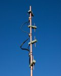
You'll notice that each dipole is on the same side of the mast but 45 degrees offset. This gives me some gain and a little bit of tilt, which is ideal for my situation.
I made this antenna from stuff I already had on hand from other antenna projects.
Dimensions for 855-860 MHz:
Mast: 1/2" copper pipe (5/8" outside diameter), at least 41" inches long
Element: 3/16" outside diameter copper tubing
Mast to Element, center to center: 1.875"
Quarter wave element length: 3"
Dipole spacing, center to center: 10.29"
For the phasing harness (see plans in post linked above), I used some RG-59U I had lying around, and using a velocity factor of .79, which gave me:
Cable "A": 8.125"
Cable "B": 13.54"
Between the phasing harness and the scanner, I used some 50 ohm Mini-8U (RG-8X?).
I used 1.125" wooden dowel for the dipole holders (painted green in photos). I drilled a 3/16" hole for the elements, and 5/8" holes for the copper pipe to slide into, and for soldering the coax to the elements (not easy). There is about an 1/8" space between the 1/4 wave elements where the coax attaches. I potted the hole where the coax connects with hot glue (see photos). There is a screw that enters the back of the dowel that clamps the dipole holder to the copper pipe.
If I were to do this again, I'd find a sheet metal screw that fits into the end of the 3/16" tubing (probably a #4) and attach the coax there. Then maybe I'd cut a 3/16" slot in end of the dowel and glue the elements in.
Since I didn't have any F connector "T" adapters, I soldered my phasing cable junctions, then potted the connections.
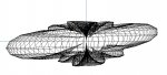
I don't have an antenna analyzer (any recommendations for one that goes up to 2.4 GHz?), so I decided to model the antenna with EzNEC (after I built it LOL!) I've attached a couple of different models, one matching the 45 degree dipole arrangement I made, and the other a standard configuration where all of the dipoles are on a single side (a good starting point).
The model shows the bandwidth being about 55 MHz where the SWR is below 1.5. The gain ranges from peaks of 9.8 DBi to 7.76 DBi from elevation -5 degrees to +10 degrees (freespace).
It was a fun project and I learned a few things in the process.")
I decided to try making this style of antenna for 800 MHz DTRS monitoring. The results exceeded my expectations.
I live in a mountainous area, and 800 MHz signals are difficult to receive. I am currently using a Yagi, but that limits me to one direction, but an omni doesn't have enough gain. The 3 sites I want to monitor are directionally about 40 degrees apart, and I don't have line of sight to any of them. They are all blocked by terrain.
You'll notice that each dipole is on the same side of the mast but 45 degrees offset. This gives me some gain and a little bit of tilt, which is ideal for my situation.
I made this antenna from stuff I already had on hand from other antenna projects.
Dimensions for 855-860 MHz:
Mast: 1/2" copper pipe (5/8" outside diameter), at least 41" inches long
Element: 3/16" outside diameter copper tubing
Mast to Element, center to center: 1.875"
Quarter wave element length: 3"
Dipole spacing, center to center: 10.29"
For the phasing harness (see plans in post linked above), I used some RG-59U I had lying around, and using a velocity factor of .79, which gave me:
Cable "A": 8.125"
Cable "B": 13.54"
Between the phasing harness and the scanner, I used some 50 ohm Mini-8U (RG-8X?).
I used 1.125" wooden dowel for the dipole holders (painted green in photos). I drilled a 3/16" hole for the elements, and 5/8" holes for the copper pipe to slide into, and for soldering the coax to the elements (not easy). There is about an 1/8" space between the 1/4 wave elements where the coax attaches. I potted the hole where the coax connects with hot glue (see photos). There is a screw that enters the back of the dowel that clamps the dipole holder to the copper pipe.
If I were to do this again, I'd find a sheet metal screw that fits into the end of the 3/16" tubing (probably a #4) and attach the coax there. Then maybe I'd cut a 3/16" slot in end of the dowel and glue the elements in.
Since I didn't have any F connector "T" adapters, I soldered my phasing cable junctions, then potted the connections.
I don't have an antenna analyzer (any recommendations for one that goes up to 2.4 GHz?), so I decided to model the antenna with EzNEC (after I built it LOL!) I've attached a couple of different models, one matching the 45 degree dipole arrangement I made, and the other a standard configuration where all of the dipoles are on a single side (a good starting point).
The model shows the bandwidth being about 55 MHz where the SWR is below 1.5. The gain ranges from peaks of 9.8 DBi to 7.76 DBi from elevation -5 degrees to +10 degrees (freespace).
It was a fun project and I learned a few things in the process.
Attachments


Last edited: