A grounding question please

MUTNAV

Active Member
Premium Subscriber
Joined
Jul 27, 2018
Messages
1,402
Ok... It's possible I'm not expressing myself clearly.

My idea is that in a 240 Volt home power system, if there is an imbalance in loads between the two phases (although I guess it's technically called a single phase system.) The imbalance goes to the neutral, which is connected to the ground at the entry panel.

Shouldn't there be be some sort of current on the ground system, although most should go to the neutral back to the transformer? AND if there is another grounded system nearby, there should be a potential difference that could be exploited?

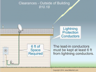
The second part of my "issues" (in a nice sense "issues") is that The N.E.C. says that the down-lead on the mast (which should have a lightning rod) can't be near the feed-line, which is just about impossible for most of us.

Maybe I'm just brain blocking the understanding of having to keep the feed-line and ground separated by a distance that isn't practical.

These two illustrations shows the general idea, a lightning down-conductor would be right next to the feedline on the mast (the TV looking one).
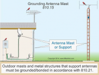
1741630533851.png

1741630556700.png

Thanks to Mike Holt for the illustrations.

Joel
 

AC9KH

Member
Joined
Nov 5, 2014
Messages
216
Location
Northern Wisconsin
Shouldn't there be be some sort of current on the ground system, although most should go to the neutral back to the transformer? AND if there is another grounded system nearby, there should be a potential difference that could be exploited?

No, because the ground does not complete the AC circuit back to the generator, transformer or inverter. The neutral does. Power will only flow on the ground in the event of a fault to ground.

The power system in question is indeed single phase, but technically split-phase because the two phases are 180° out of phase. A split-phase 240V electric motor only requires the two phases to it to run. No neutral or ground required. However, without the ground conductor to it, in the event of a ground fault in the motor the motor will become "hot" and you do not want to touch it. The neutral is only used for half-voltage (120V) loads that require a return path to the source.

The source, in this case, is not your service entrance panel or the powerplant. It is the secondary winding in your transformer that feeds your service panel. That winding has a center tap for the neutral.

And yes, there is differences in ground potential, but this is not "free" power. It is due to leaks in wiring, transformers, insulators etc.. It is a man-made phenomenon due to running too many wires all over tarnation with a national grid system that's only about 40% efficient due to I^2R losses and "leak" losses to ground.
 

MUTNAV

Active Member
Premium Subscriber
Joined
Jul 27, 2018
Messages
1,402
I take free power to mean anything I personally am not directly paying for, ie a crystal radio getting "free" power from radio waves.

Thanks
Joel
 

AC9KH

Member
Joined
Nov 5, 2014
Messages
216
Location
Northern Wisconsin
I take free power to mean anything I personally am not directly paying for, ie a crystal radio getting "free" power from radio waves.

You can string a wire under a HV powerline and get "free" power from it with capacitive coupling of the EMF off the line. But I don't know how practical it is. I would imagine if you put a voltage regulator downstream of the rectifier you could probably charge a battery with it.

Edit: I'll add that capacitive coupling with earth ground under HV powerlines "leaks" millions of dollars worth of electricity every year. It is an elaborate network of 60Hz radiators strung all over tarnation.

 
Last edited:

MUTNAV

Active Member
Premium Subscriber
Joined
Jul 27, 2018
Messages
1,402
You can string a wire under a HV powerline and get "free" power from it with capacitive coupling of the EMF off the line. But I don't know how practical it is. I would imagine if you put a voltage regulator downstream of the rectifier you could probably charge a battery with it.

Edit: I'll add that capacitive coupling with earth ground under HV powerlines "leaks" millions of dollars worth of electricity every year. It is an elaborate network of 60Hz radiators strung all over tarnation.

I've always wondered though, would the 60hz radiation be the best "target" (I NEVER intend on doing anything like this, this is more of a mental exercise), or would 180Hz be more appropriate, depending on location, since (I assume) it's 3 phase, and there may be overlapping fields?

Thanks
Joel
 

AC9KH

Member
Joined
Nov 5, 2014
Messages
216
Location
Northern Wisconsin
I've always wondered though, would the 60hz radiation be the best "target" (I NEVER intend on doing anything like this, this is more of a mental exercise), or would 180Hz be more appropriate, depending on location, since (I assume) it's 3 phase, and there may be overlapping fields?

I don't think so. It's still 60Hz on every phase, just that they're 120° separation. The simplest three-phase transmission line will have three conductors on the bottom, with a single ground conductor on top. You'll notice that ground conductor is connected to earth with ground rod at every pole and it's conduit'd up high enough so you can't touch it. And there's a sign on the pole that says it's really stupid to try to climb up the pole and touch that ground wire. That's because there's current on it. It's purpose is not to ground anything to it - it's there in the hope that if lightning strikes the line it will hit the ground wire and get shunted to earth instead of blowing transformers. This scheme only works about 20% of the time. Usually the EMF from the strike sends a big surge down the lines anyway and blows equipment that I work on all to smithereens before it burns the fuse links off on the pole pigs.

Or the other one that will cause me to fire up the Cat in my service truck and head out to fix stuff - somebody hits a power pole with a car and you get a phase-to-phase slap on the lines.

The service grounds you are concerned with are derived at each service entrance and they are in no way shape or form connected to those transmission line grounds.
 
Last edited:

AC9KH

Member
Joined
Nov 5, 2014
Messages
216
Location
Northern Wisconsin
Joel, this guy likes to fiddle with the near field radiation from the powerlines. String a EFW and get over 1,100 volts on it.


I think it is a good demonstration of how your radio antennas work. RF is the same thing, just at higher frequency. Also a good demonstration of why care must be taken when running feedlines, antennas or grounds. And maintaining separation between your antennas and feedlines with certain conductors. Any wire you run, including grounds, can become antennas. A Beverage antenna is a just a long wire terminated to ground at one end with a resistor approx equal in resistance to the antenna as a feedline (usually around 600 ohms). Unlike a resonator, a Beverage is a directional LF/MF traveling wave antenna, which is basically what the fellow in the video constructed although he didn't terminate the other end to ground to match impedance for a receiving antenna on a radio.

Modern society has created an elaborate network of radiated "noise" and electric currents "leaking" into ground from the national utility grid. Roughly 60% of all the power generated is lost before it gets to the load.

This is why it's important to ohm out grounds instead of blindly driving ground rods and running "bonding wires" all over tarnation. Create ground loops where fault current can travel in a coil (loop) and you just created more problems than you solved with your extra ground wires.

So people go, "oh, if you don't drive that ground rod then you got no lightning protection." I just laugh. LPS's are WAY more complex than just a ground rod on an antenna mast and they have nothing to do with NEC safety grounds. If you're going to drive a ground rod for an antenna mast you'd better make sure the antenna that's on it is not electrically part of the mast, so the mast would be "floating" above earth ground. Now you have a reason to ground that mast. But if it's so far away from the rest of your grounds that there's no chance of getting a shock off it due to two different potentials, now it has to have its own ground that equalizes it with local ground potential.

You can put up a 43' ground mounted vertical and the radiator on that antenna is RF isolated from the RF ground because it has to be. It can even be a flagpole antenna with a flag flying on it. However, your 43' vertical likely has an unun transformer on it. If you ohm out the radiator on it to the ground plane you'll find zero DC ohms. Why? Because of the transformer secondary in the unun. This is the same antenna I got except mine is 120ft tall. And this is completely legal for NEC. If anybody touches it while you're transmitting they'll probably have a shocking experience, especially if you're driving it with an amp. And there should be a safety fence around it so people have to go to great lengths to experience what an RF burn is like. But if lightning strikes it? You'd better hope you had your feedline disconnected from it or it will blow your radio right off the desk. Even a proximity strike produces many thousands of volts on that antenna. The old timers, back when 160m was the original ham radio band, used to disconnect their antenna and put the ends of the feedline in a glass jar.
 

K5MPH

Member
Joined
Jul 16, 2003
Messages
1,667
Location
Brownsville Texas,On The Border By The Sea.
Joel, this guy likes to fiddle with the near field radiation from the powerlines. String a EFW and get over 1,100 volts on it.


I think it is a good demonstration of how your radio antennas work. RF is the same thing, just at higher frequency. Also a good demonstration of why care must be taken when running feedlines, antennas or grounds. And maintaining separation between your antennas and feedlines with certain conductors. Any wire you run, including grounds, can become antennas. A Beverage antenna is a just a long wire terminated to ground at one end with a resistor approx equal in resistance to the antenna as a feedline (usually around 600 ohms). Unlike a resonator, a Beverage is a directional LF/MF traveling wave antenna, which is basically what the fellow in the video constructed although he didn't terminate the other end to ground to match impedance for a receiving antenna on a radio.

Modern society has created an elaborate network of radiated "noise" and electric currents "leaking" into ground from the national utility grid. Roughly 60% of all the power generated is lost before it gets to the load.

This is why it's important to ohm out grounds instead of blindly driving ground rods and running "bonding wires" all over tarnation. Create ground loops where fault current can travel in a coil (loop) and you just created more problems than you solved with your extra ground wires.

So people go, "oh, if you don't drive that ground rod then you got no lightning protection." I just laugh. LPS's are WAY more complex than just a ground rod on an antenna mast and they have nothing to do with NEC safety grounds. If you're going to drive a ground rod for an antenna mast you'd better make sure the antenna that's on it is not electrically part of the mast, so the mast would be "floating" above earth ground. Now you have a reason to ground that mast. But if it's so far away from the rest of your grounds that there's no chance of getting a shock off it due to two different potentials, now it has to have its own ground that equalizes it with local ground potential.

You can put up a 43' ground mounted vertical and the radiator on that antenna is RF isolated from the RF ground because it has to be. It can even be a flagpole antenna with a flag flying on it. However, your 43' vertical likely has an unun transformer on it. If you ohm out the radiator on it to the ground plane you'll find zero DC ohms. Why? Because of the transformer secondary in the unun. This is the same antenna I got except mine is 120ft tall. And this is completely legal for NEC. If anybody touches it while you're transmitting they'll probably have a shocking experience, especially if you're driving it with an amp. And there should be a safety fence around it so people have to go to great lengths to experience what an RF burn is like. But if lightning strikes it? You'd better hope you had your feedline disconnected from it or it will blow your radio right off the desk. Even a proximity strike produces many thousands of volts on that antenna. The old timers, back when 160m was the original ham radio band, used to disconnect their antenna and put the ends of the feedline in a glass jar.
He never showed how many Amps and Watts he was getting just the voltage.........
 

AC9KH

Member
Joined
Nov 5, 2014
Messages
216
Location
Northern Wisconsin
He never showed how many Amps and Watts he was getting just the voltage.........

No, he had both voltmeter and ammeter on the DC side of the diodes and filters. He calculated it at about 60 milliwatts. The same guy also has another video where he lights up various florescent light tubes with a makeshift antenna under the powerlines. Put a resonant wire near those lines, which would be 1,561 miles long @ 60Hz for a half-wave (minus velocity factor), I can imagine you could generate some pretty serious power on it.
 

MUTNAV

Active Member
Premium Subscriber
Joined
Jul 27, 2018
Messages
1,402
No, he had both voltmeter and ammeter on the DC side of the diodes and filters. He calculated it at about 60 milliwatts. The same guy also has another video where he lights up various florescent light tubes with a makeshift antenna under the powerlines. Put a resonant wire near those lines, which would be 1,561 miles long @ 60Hz for a half-wave (minus velocity factor), I can imagine you could generate some pretty serious power on it.
Not a half wave, but a WWVB passive antenna booster can be made resonant in a couple of feet.

If I remember right, it doesn't take an antenna to get a florescent light it illuminate, just hold it up.

Ok.... a quick search showed a father doing this with his kids.


Thanks
Joel
 

AC9KH

Member
Joined
Nov 5, 2014
Messages
216
Location
Northern Wisconsin
Lightning may have traveled 5mi or more to reach your antenna, placing your coax connector in a jar isn't going to stop it.

I don't know if they even had coax back in those days. I think they just used wire feeders. Putting the ends of the feeder in the glass jar for lightning used to be pretty common, I suspect to prevent arcing on the wires from starting a fire in the shack.
 
Top