
A friend owns a company that is designing AI software for engineering purposes and asked me to do some test runs on it. After having the system scrounge the internet for information on antenna designs I then asked it to design a small 20-1300MHz coiled dipole antenna that required no ground plane. After crunching the numbers for a while it turned out a design for an overall 24 1/4" dipole.
Got the wire diameter it suggested and then headed to another friends shop that works on racing cars and has all the equipment I needed. Turned the coils on the wire as directed by the AI design, and made both halves of the antenna. Connected both halves to a non-conductive center piece and soldered the LMR coax to both halves. Then placed the antenna into a 27 inch piece of 1/2 inch pvc, capped the top end, and placed a 1/2 inch T on the bottom end with the coax run out thru it.
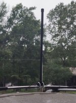
Next was mounting the antenna on my suv luggage rack, which required two rather large U-clamps because of the width of the luggage rack.
Tested out the antenna on my SDS200 against my 20-1300MHz mag mount antenna. RSSI strength was any where from 10-25 points better on the home made dipole than on the mag mount depending on the range of the system being monitored. This was while parked in my driveway and riding around the neighborhood. I am going to take the antenna on a road trip and see how it works on the road.
My next step will be to build a second antenna, place it in pvc, cap both ends and raised it up on a pole the same height as my Omni X and compare the two antennas. If I get good results will then raise it up over a tree limb about 50 feet in the air and see how it does.
So far pleased with the results and hope the road test and pole tests are just as promising.
Got the wire diameter it suggested and then headed to another friends shop that works on racing cars and has all the equipment I needed. Turned the coils on the wire as directed by the AI design, and made both halves of the antenna. Connected both halves to a non-conductive center piece and soldered the LMR coax to both halves. Then placed the antenna into a 27 inch piece of 1/2 inch pvc, capped the top end, and placed a 1/2 inch T on the bottom end with the coax run out thru it.
Next was mounting the antenna on my suv luggage rack, which required two rather large U-clamps because of the width of the luggage rack.
Tested out the antenna on my SDS200 against my 20-1300MHz mag mount antenna. RSSI strength was any where from 10-25 points better on the home made dipole than on the mag mount depending on the range of the system being monitored. This was while parked in my driveway and riding around the neighborhood. I am going to take the antenna on a road trip and see how it works on the road.
My next step will be to build a second antenna, place it in pvc, cap both ends and raised it up on a pole the same height as my Omni X and compare the two antennas. If I get good results will then raise it up over a tree limb about 50 feet in the air and see how it does.
So far pleased with the results and hope the road test and pole tests are just as promising.
 n
n