Antenna - S21 Analysis

Status
Not open for further replies.

Mike_G_D

Member
Joined
Dec 19, 2002
Messages
1,241
Location
Vista, CA
I can't be all that good, I missed that he was using S21 and not S11. I'm a complete failure. Mike_G_D is the one to follow.

Oh good grief! My ego has been trashed, squashed, and largely obliterated by life at this point so this comment presents like a weird anomalous noise bump largely of minor significance... but, to be courteous, and because I really do respect you considerably (no way Jose' do I have anywhere near your practical experience with antenna design, testing, and analysis) I express my slightly self conscience "thank you"!

Anyway, seriously, I did notice you overlooked that S21 error but, especially in your case, I attributed it to a simple oversight common amongst all of us semi-evolved simians.

No more ego stroking and back to the discussion at hand.
 

ScubaJungle

Active Member
Joined
Mar 11, 2020
Messages
618
Location
West Central Florida
Ah okay, I had the idea that adding a ground would somehow reflect this increase in performance, but I see what you are saying. Its basically tricking the VNA into a false reading, while the actual results are poor. I also understand what you said about it not being "exact," as some of the readings dont align with what actually works best, etc. I mainly have been using it to get a general idea of what lengths and such will work, and then base the rest off actual performance.
I do make sure that I am never touching the antennas or too close to them when I do the tests to avoid this though, and the handheld antenna readings were all taken without any coax. I re-calibrated the device with coax to see how it affected the dipole, yagi, and discone, which I can upload later. Thanks for the help.
-------------------------------


Thank you for the detailed response and great information that cleared up a lot of info I wasnt sure of. I realized the subject line was wrong after fixing my initial mistake where I was using the wrong port. There's a surprisingly large amount of wrong information on Google about this device, I guess due to the price everyone thinks they are an expert.

Some, though not too much of this is somewhat familiar from my college chemistry and calc/geometry classes, but this goes far past what was covered.
I recalibrated the device with the coax for the "base" antennas, and the handhelds I just screw right into the port, so I will see how the readings differ. Now that I look back, I did realize a difference when using the coax rather than with the handhelds screwed right in - the smith chart showed a much larger circle, and I believe it went around twice also, whereas I am pretty sure the circle was tiny with the directly screwed in handhelds. Im not sure if that is relevant, and Im going to have to do some reading on the Smith chart past the basics of the labels of the planes.
Even if the dipoles do perform well without a ground, would I see increased performance with one, or would it be very minimal? I would like to try it with the Diamond RH789 though, and see how the performance is affected,

I didnt realize the absolute value chart was for impedance, so I added that chart to the "analysis screen" and will see how those values are effected with coax and proper calibration, as well as the figures from my different antennas.

I didnt expect to learn so much from this purchase, but Im glad I made it. Lots of good information here, and a lot more reading I have to do. I really like understanding how things work, as well as how to utilize potential and make things better, so this is very interesting to me. Its not something I will probably ever understand fully, unless I went back in time and changed my university major from animal biology to electrical engineering, but I think I can make a lot of improvements with my scanning and ham/gmrs/etc set ups and get more enjoyment out of it, along with any time this knowledge can come in handy in the future.

Thanks to all of you guys for the help. I will do some more updated tests with the proper calibrations and anything else I find. These tests aren't meant to be a professional analysis of any of these antennas -instead a learning experience in using this device and the surrounding topics, as well as info for anyone else looking to learn about this.
 

Mike_G_D

Member
Joined
Dec 19, 2002
Messages
1,241
Location
Vista, CA
All good. It helps to have a decent concept of vector addition, imaginary components of values, etc. So it sounds like you're on the right road.

In the electronics world, the "i" imaginary component of a value as in 3-i5 is replaced with a "j" lower case. The reason is that "i" represents current in electronics engineering, in the lower case usually AC current with a frequency associated with it. So, to avoid confusion, in the electronics engineering field, "i" was replaced with "j". But in mathematical terms, they represent the same thing - the imaginary component of the value. Same basic use of the usual x and y graph but with the origin usually centered or normalized to the system desired impedance which is usually 50 ohms or 75 ohms.

As you may know, when you add vector values you can use either real+imaginary or magnitude and angle approaches.

So, when you see a reference to a "polar plot" when using VNA's that means the presented graph will show a magnitude and phase angle.

I've never been as good at utilizing a polar plot as I am with using a Smith Chart. But you use what you are most comfortable with.

The idea with impedance matching in the RF world is to keep the imaginary part as low as possible (the "reactive" component) and make the resistive part as close to the desired system impedance as possible (50 or 75 ohms typically).

With antennas, you try and get them to present a nice 50 or 75 ohm impedance with small or no reactive component that the transmitter or receiver is designed to work with. The further you get away from that the worse the presented impedance will be relative to 50 or 75 ohms purely resistive.

Most antennas are only "purely resistive" or close to that at their center resonance frequency point. That doesn't mean they won't work well outside of that but usually, depending on the design, it will get worse and worse the further away from the center of resonance.

Depending on the design of the antenna, the loss from impedance mismatch may not be so bad that the gain of the antenna can't significantly overcome it. So a perfect match isn't usually an absolute necessity nor is it practically possible across all frequencies that may be in use for a given antenna.

You should, of course, understand how to calculate wavelength for a given frequency. In case you don't know, in pure form it's the speed of light divided by the frequency. For all practical purposes when dealing with common LMR frequencies that are usually measured in MHz you can reduce and approximate that down to a simple 300/freq. in MHz. But that's still for "in free space" as out there in space. Air here can change things. The usual approximation that tries to fold in compensation for some of this is 468/freq. in MHz for a half wave length. Half wave antennas form the basic starting point for the vast majority of practically usable designs. Your TV rabbit ears is a simple half wave dipole, for example.

A 1/4 wave spike as most handheld and mobile antennas are is a modification of this that uses a (ideally infinite) ground plane as the "second half" of the antenna. For a car that is the metal car body. For a handheld it is the metal casing of the handheld radio (plus, during typical operation, the coupling of your hand to the case of the radio). Generally, while in the air above ground in the form of a base station type antenna, you use ground plane radials to provide the ground plane, the more the better. If the radials are at right angles relative to the radiating 1/4 wave vertical element then the impedance is (I think, as I recall - PRC Guy can correct me if I'm wrong) around thirty-something ohms. But if you bend the radials down to a 45 degree angle relative to the 1/4 wave radiator you get closer to that magical 50 ohms. Another approach, especially at lower frequencies and therefor longer wavelengths, is to mount the vertical 1/4 wave element at ground level and use the actual earth ground as the ground plane. But this really only works best if you also spread out as much radial wires as possible along the ground radiating away from the base of the antenna. Depends on how good the ground resistivity is where you're mounting the antenna. Among other things. Not my area of expertise here so...

A half wave dipole fed in the center presents around a 70 ohm impedance at center resonance. Hence the common use of 75 ohm coaxial cable and baluns for such antennas. A half wave antenna is also a "balanced" design and, to properly attach it to an "unbalanced" lead such as coaxial cable, you should use a "balun" which is short for "balanced to unbalanced". Again, when you have a half wave dipole vertically mounted the "bottom" element is the "other" 1/4 wave "half" of the antenna that the ground plane creates for the 1/4 wave antennas described above. Because a 1/2 wave dipole mounted well above ground has both 1/4 wave elements balanced and symmetrically mirror images of each other a good dipole should out-perform a 1/4 wave ground plane all other things being equal and at the center of resonance. The coax should be fed at a right angle to the antenna meaning that it extends out 90 degrees from the vertical away from the antenna for a vertically polarized arrangement. You don't want to run the coax down parallel to the lower 1/4 wave element nor do you want a metal mast too close to that element. This is why most such designs have an arm at 90 degrees from vertical for mounting to a mast and the coax runs away from the antenna along that arm until again going vertical down the mast.

There is really no need at all for a ground plane for a true half wave dipole mounted in the air. The closer to the ground it gets, though, the more "squashed" the usual "doughnut shaped" approximate torus radiation pattern gets and, I need help here, but I think that you might get more elevation angle to the pattern. Again, I differ to PRC Guy here.

There are other variations like a coaxial sleeve dipole that uses a half wave sleeve for the lower element with the coax running up inside to connect at the junction between the two 1/4 wave elements. No balun is usually needed here as the sleeve effectively "decouples" the unbalanced coax from the radiation of the antenna which is why it is also sometimes called a "decoupling sleeve".

But for small 1/4 wave spikes you really should have a ground plane of some type suitable for the frequency of interest. At low frequencies like CB and VHF low that is really tough. Pretty much impossible due to the long wavelengths of the frequencies. Handheld radios at those frequencies using physically and practically small antennas do not perform very well for that reason. At UHF and up, though, presuming the radio has a decent metal body content, it gets much much better. This is why most modern LMR usage that relies a lot on handheld portable radios is in the VHF high and above frequency ranges. If low band is used, there is often a vehicular repeater that operates in much higher frequency ranges and allows a much higher frequency handheld to connect to the low band mobile radio in the car as in the CHP vehicles here in California.

The body of your portable VNA may have sufficient metal to act as a groundplane for the higher UHF ranges but you should use some extra metal for the lower ranges. About 18 inches in diameter for the VHF-High 150 MHz band for example.

Some UHF and higher handheld antennas, due to the small wavelengths involved, use a coaxial sleeve or end-fed half wave design which may give them a slight improvement over the typical 1/4 wave spike and they also do not need a separate groundplane to work well though it won't hurt them if they also have one.

There are "tricks" that can be used to physically shorten a 1/4 wave antenna to smaller sizes and still make them work sort of ok. They usually involve some kind of "loading" which amounts to a form of impedance matching to make the antenna "appear" to be electrically equivalent to a real 1/4 wave to the radio. Most handheld "rubber ducks" use a "continuous loading" which amounts to a helical wound wire all along the length of the antenna to allow, for example, a VHF-High 155 MHz 18 inch 1/4 wave to be reduced to a total physical length of 6 inches or so. Needless to say, this results in a negative gain compromise solution but it works well enough when properly implemented in a moderate to strong signal environment. Mobile car antennas have a little more flexibility and can use base and center loading coils which you often see when physical size needs to be reduced. Top loading is possible, as well, but seldom used due to mechanical issues posed by such designs mounted on moving vehicles with wind loads at speed.

Your VNA isn't being "tricked" when you "added a ground". That's simply what it is. Some kind of ground plane versus no ground plane at all are going to yield different results for a given 1/4 wave based antenna design.

Something else to know - though proper impedance matching is very important to transmitter amplifiers as you want the maximum power from the amplifier delivered to the antenna, it is really less so for receivers. It's a question of "small signal amplifier design" versus "power amplifier design" Two different beasts, believe me!

In general, for receivers, the main idea is to get the most signal voltage level (not power as with a transmitter) into the small signal receiver amplifiers as possible. Unlike with power amplifiers in transmitters, if you look at the math, in theory you could have a very high impedance receiver antenna port relative to the antenna and that should provide maximum voltage level. But for various reasons, including the effect of the characteristic impedance of the coaxial cable used, amount of noise in the system, and the simple fact that you are making a design that uses a single port for the antenna connection for both the transmitter and the receiver in a typical transceiver you generally still stick to designing around a common 50 ohm resistive ideal design point for both the transmitter and the receiver. So in the RF world impedance matching is the name of the game for both transmission and reception. But you do still see high impedance antenna ports on some receivers such as low frequency short wave (HF and lower) receivers and these ports are typically attached to random wire antennas like "long wires" that are not "matched" to the receiver.

But for broad band large frequency range VHF and above receivers like your typical scanner, I assure you that if you were to connect your VNA to your antenna port of the scanner (careful if you do this as you don't want the level of the test signal from the VNA to overload or damage your radio!) it is unlikely that you would see a nice perfect 50 ohm load impedance at any frequency within its designed for range let alone along the entire radio frequency coverage! The design criteria for wideband receivers is usually to make the receiver work well when connected to a low impedance unbalanced source like a typical 50 ohm based antenna. That does not at all mean that the load impedance of the receiver's first stage amplification (or in some cases the first mixer itself but usually with some kind of buffer amp ahead of it) will present a true 50 ohm resistive load to an incident signal. So don't be either surprised or alarmed if you do this and see some weird non-50 ohm resistive result at the antenna port of your favorite receiver no matter what frequency you choose to tune it to. And, by the way, if you do do this make sure to turn the receiver on as most amplifiers and other active devices will present very different load characteristics to an incident signal when powered off versus when powered on.

-Mike
 

Ubbe

Member
Joined
Sep 8, 2006
Messages
9,046
Location
Stockholm, Sweden
All scanners needs to be powered on when measuring their impedance characteristics, as they use several bandpass filters that switch in using forward biased switching diodes. The scanner needs to be set to a frequency in the band you want to measure to engage the correct bandpass filter. I have yet to see a scanner that has an amplifier or mixer directly at the antenna port without any kind of filtering.

Most wideband radios use tracking filters with varicap diodes that needs to be set to the exact frequency you intend to test for its impedance value. A 400MHz UHF radio needs to be checked at 400-425-450-475Mhz frequenciences to see that the tracking is calibrated properly to the frequency.

The only receiver you can test without powering them on are probably narrow band radios or basestations that only work withing a couple of MHz. But then it could a a mixer or amplifier that gives a different load depending of if it's powered on or not. So, always have the device powered on as VNA's are not power transmitters, they are smallsignal generators that cannot harm any receiver.

/Ubbe
 

ScubaJungle

Active Member
Joined
Mar 11, 2020
Messages
618
Location
West Central Florida
I was wondering what the j was, but I kind of just figured it was something different I would need to learn. Now that makes more sense looking back at it. Actually, all of this is making a lot more sense to me with this last post. There's a lot of bells going off with things I've read or seen that I didn't quite understand before too.
I didnt realize that dipoles had the coax come out at a 90 degree angle for a reason, I have it kind of just hanging down, so Im going to make sure that it comes out at least a bit at that angle. I know it probably wont make a huge difference, but might as well use everything properly to get the best performance. I was also wondering why almost all the dipoles I see have 75ohm coax, and that makes perfect sense now.
I really didn't realize how important/useful impedance was in this setting. This is all some really great information, so thank you. This is the type of info that could be really useful in this hobby.

---------


I am going to try testing the scanner too - I didnt really consider this before since its not something I can "change," but it would be useful to know. I wonder if anyone had posted any values on this for a 436? Thanks!
 

ScubaJungle

Active Member
Joined
Mar 11, 2020
Messages
618
Location
West Central Florida
86622
This is a quick one of my 800mhz yagi + the lmr400 cable I use with it. I just did it quick without calibrating in the coax, but this seems a lot more reasonable. I guess the cheap coax is that bad?
 

Mike_G_D

Member
Joined
Dec 19, 2002
Messages
1,241
Location
Vista, CA
Sorry - this is the cheap coax that comes with the dipoles
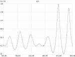
Ah! Ok, as to coax - you usually do a S12 and S21 on that because you are usually characterizing the thru loss (the loss characteristics of the coax across a specific frequency range). If you are just looking at the coax at one end with an S11 measurement with the other terminated into an open or a load it won't really tell you much. Depending on the length of the coax you will see something like this as the reflected energy bounces back and forth with an open or short at the far end so maybe that's what you did.

Do a S12 and S21 two port analysis of the coax and look at dB loss. That can tell you a lot. Each end of the coax attaches to an S port on the analyzer - one end on S1 and the other on S2. Be sure, in this case, to calibrate the analyzer right at the terminals and, if possible, use a calibrated thru standard as well as an open, short, and load. If you don't have one it might still be close enough depending on how the analyzer is set up.

-Mike
 

Mike_G_D

Member
Joined
Dec 19, 2002
Messages
1,241
Location
Vista, CA
Ok, I saw your last post after I typed up my reply to your earlier one. Just fyi - I am a very slooooow hunt and peck typist!:-( Sorry!

What did you have the other end of the "cheap" coax attached to when you got that first all-over-the-place graph? If an antenna, which one? Was it also the yagi? Or an open, load, or short standard?

-Mike
 

ScubaJungle

Active Member
Joined
Mar 11, 2020
Messages
618
Location
West Central Florida
In retrospect, I guess it is pretty obvious I should've attached both ends, lol.
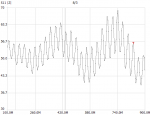
I had an open, no antenna. I just redid it with open, short, load and thru calibrated, with both ports used, and the results look a lot better.
86623
 

Mike_G_D

Member
Joined
Dec 19, 2002
Messages
1,241
Location
Vista, CA
In retrospect, I guess it is pretty obvious I should've attached both ends, lol.
I had an open, no antenna. I just redid it with open, short, load and thru calibrated, with both ports used, and the results look a lot better.
View attachment 86623
Mmmnnn...yeah...but not telling you much. You really need to do a through loss not |Z|. Try a basic S12 measurement in dB over the same frequency range. You don't really need to do an S21 also as it should be the same but you can if you want to. You should see a nice clean rising loss line across the range with loss getting worse as the frequency increases. Impedance, in this case, is not as valuable. Set your scale to normalize at 0dB loss as shown by the calibrated thru standard and then replace the thru with the coax and note the difference. You may have to play with the graph scale to get the best readable picture.

-Mike
 

ScubaJungle

Active Member
Joined
Mar 11, 2020
Messages
618
Location
West Central Florida
Mmmnnn...yeah...but not telling you much. You really need to do a through loss not |Z|. Try a basic S12 measurement in dB over the same frequency range. You don't really need to do an S21 also as it should be the same but you can if you want to. You should see a nice clean rising loss line across the range with loss getting worse as the frequency increases. Impedance, in this case, is not as valuable. Set your scale to normalize at 0dB loss as shown by the calibrated thru standard and then replace the thru with the coax and note the difference. You may have to play with the graph scale to get the best readable picture.

-Mike
Oh I see now - I have a reading of that from the last one with this - I just need to set 0 as the standard. Not sure why it didnt do that when I calibrated though

86629
 

Attachments

  • thruloss.png
    thruloss.png
    10.1 KB · Views: 1

Mike_G_D

Member
Joined
Dec 19, 2002
Messages
1,241
Location
Vista, CA
Something of note here - a piece of coax can
Oh I see now - I have a reading of that from the last one with this - I just need to set 0 as the standard. Not sure why it didnt do that when I calibrated though

View attachment 86629
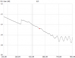
Woof! That looks bad if that is real! That's a HUGE loss even at 100 MHz! I'd expect something on the order of a few dB at most. I am guessing that something is not right with the calibration on this or else the cable is super nasty and/or has bad connectors, etc. How long was the coax? Even at 100 feet this looks way too awful!

-Mike
 

ScubaJungle

Active Member
Joined
Mar 11, 2020
Messages
618
Location
West Central Florida
Something of note here - a piece of coax can

Woof! That looks bad if that is real! That's a HUGE loss even at 100 MHz! I'd expect something on the order of a few dB at most. I am guessing that something is not right with the calibration on this or else the cable is super nasty and/or has bad connectors, etc.

-Mike
I think that it should be starting at 0, and not -12 (or at least I hope!), but I'm going to re-do the calibration and check another piece of it to make sure.

Edit: I found the issue. This thing loves to reset when I run a sweep, so that last one is garbage.
The coax is only like 6 feet long, so it definitely shouldnt be that bad.

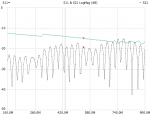
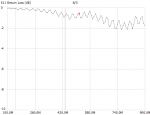
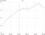
This nanovna sometimes resets to the non-calibrated state when I run a sweep from the computer program, Im not sure why. I got it to work, although the S21 measurement looks strange. S11 looks normal though, but Im not sure if that is relevant here.
86630
86631
 
Last edited:

Mike_G_D

Member
Joined
Dec 19, 2002
Messages
1,241
Location
Vista, CA
I think that it should be starting at 0, and not -12 (or at least I hope!), but I'm going to re-do the calibration and check another piece of it to make sure.

Edit: I found the issue. This thing loves to reset when I run a sweep, so that last one is garbage.
The coax is only like 6 feet long, so it definitely shouldnt be that bad.

This nanovna sometimes resets to the non-calibrated state when I run a sweep from the computer program, Im not sure why. I got it to work, although the S21 measurement looks strange. S11 looks normal though, but Im not sure if that is relevant here.
View attachment 86630
View attachment 86631
No, actually, they both agree with each other in that they are both really bad! Remember that, if what you are describing is correct in terms of the setup, you are just looking at a 6 feet piece of coax. You should see a very high return loss meaning very little reflected energy due to a nice matched load thru a cable that should be of the same or close characteristic impedance and very little to no thru loss. These graphs show the exact opposite so something is definitely wrong either in the cable or the test setup. Without being there it's limited how I can help. But I think you're starting to get the idea. A VNA for absolute beginners isn't usually easy to master until a number of concepts get well understood. Considering this is all pretty new to you even with some goofy results I think I'm seeing progress. Don't give up or get frustrated - a VNA is a really valuable tool once mastered. But if those results are real and not a result of a either a goofed calibration or incorrect test setup then that cheap coax is only good as a S&M toy or a whip for swiping aberrant small animals that you are irritated with! Otherwise - toss it as far away as possible. But I think something else is off - S21 (or S12) should not get better as the frequency increases - definitely should be the exact opposite!

-Mike
 

ScubaJungle

Active Member
Joined
Mar 11, 2020
Messages
618
Location
West Central Florida
Lmao! I am definitely getting the hang of it more-so than before, but I am definitely a bit stumped on this. I would love to test my LMR400 coax to compare it, but I don't have a UHF-to-SMA connector to get the other side connected. If this is that bad, I wonder if I would be able to replace it, considering it is routed right into the balun. I also wonder how much better this antenna would be if the cable were better since it already performs really well (at least I think so, I am picking up Disney's trunked system in Tampa). Im going to try this again tomorrow - hopefully I am just tired and doing something stupid. but I have a feeling it is exactly as I said - cheap coax, lol.
Thanks for all the help!
 

Mike_G_D

Member
Joined
Dec 19, 2002
Messages
1,241
Location
Vista, CA
Lmao! I am definitely getting the hang of it more-so than before, but I am definitely a bit stumped on this. I would love to test my LMR400 coax to compare it, but I don't have a UHF-to-SMA connector to get the other side connected. If this is that bad, I wonder if I would be able to replace it, considering it is routed right into the balun. I also wonder how much better this antenna would be if the cable were better since it already performs really well (at least I think so, I am picking up Disney's trunked system in Tampa). Im going to try this again tomorrow - hopefully I am just tired and doing something stupid. but I have a feeling it is exactly as I said - cheap coax, lol.
Thanks for all the help!
No worries - that's kinda what I was kinda going to suggest - walk away and come back later after a good rest and/or sleep. For you this is just a hobby and shouldn't get overly frustrating. You aren't trying to prepare for an all day RF engineering interview at Qualcomm, Hughes, or TI tomorrow (been there and done that). Have fun and learn along the way and you'll be ahead of the game.

-Mike
 
Status
Not open for further replies.
Top