AOR AR8600 MKII IF Out Question

dsalomon

Member
Premium Subscriber
Joined
May 6, 2003
Messages
218
Location
Brooks, GA
Hello all. I just bought a new to me AR8600 MKII. I have it all hooked up, programmed and running. It's a FANTASTIC wideband receiver. For digital voice, I am taking the IF Out connected to my AOR AR-DV10. In order for this to work, the 8600 must be in WFM mode. The documentation states that the IF Out can be changed to work in any mode, but that "workshop" work is necessary. I found the instructions for the 8600 to do this - it's moving a resistor from one location to another (R500 to R501, to be precise). However, I believe this is for the ORIGINAL 8600, not the MKII because I can't find R500 or R501 on the boards or in the service manual. I sent a note to AOR asking for the mod for the MKII, but haven't received a response (no surprise).

Does anyone have the correct info to make this mod?

My reason for wanting this is to be able to have the receiver in USB mode for the IF Out to connect to a SDR and do HF digital decoding (in addition to VHF audio digital decoding).

73 - David, AG4F
 

G8OEO

Member
Joined
Mar 23, 2020
Messages
64
Location
Northumberland UK
Love to help but I haven’t looked at doing this mod on my own receiver.
I now have the mk2 service manual but can’t find the original 8600 version to see how much has been changed.
The mod must be something to do with IC38 switching and/or something being enabled in IC40.
 

dsalomon

Member
Premium Subscriber
Joined
May 6, 2003
Messages
218
Location
Brooks, GA
Love to help but I haven’t looked at doing this mod on my own receiver.
I now have the mk2 service manual but can’t find the original 8600 version to see how much has been changed.
The mod must be something to do with IC38 switching and/or something being enabled in IC40.
Thanks for the reply. I'll keep looking. In the original 8600, it was simply moving a resistor from one pad to another. I also have the MK2 service manual, but I can't figure out from that what needs to be done. I have instructions for the original 8600 (attached), but I can't find those resistors in the MK2 (and the board layout isn't the same). AOR makes this so hard.
 

Attachments

  • 8600_if.pdf
    69.6 KB · Views: 9

AOR-262

Member
Joined
May 10, 2016
Messages
307
@dsalomon

The 8600 Mk 2 is no longer supported by AOR and it's highly unlikely they will respond to your email - and in particular, they would be reluctant to give advice on performing a hardware modification.

You can achieve an all modes output by performing a hardware mod. to the receiver. This requires a level of skill to do this. One mistake with the soldering and you've gotten yourself a massive clean up job. If you're not confident with performing soldering to small components, it be best someone with better skill for the job.

Some background info. for you:

By factory default, the WFM heterodyne is used to generate a 10.7MHz IF output. IF output is enabled in WFM mode only, but to use the IF output in all modes, a zero Ohm link needs to be moved inside the radio, this requires the use of a soldering iron. This arrangement is designed to minimize the potential for internally generated spurii when the 10.7MHz IF output is not going to be used.

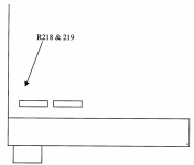
To enable the output on all modes, simply remove resistor R218 (0 Ohm jumper) and fit R219 (0 Ohm jumper). These resistor positions are located on the large main receive board on the underside of the set.

To gain access, remove the top and bottom covers. Then remove the top and bottom chassis covers (three screws down each edge of both
covers and three black threaded screws through the board. Don’t forget to unplug the speaker wire (it plugs in J7, the other socket is for the optional battery). With the set upside down and the front panel facing you R218 and 219 are located in the front left hand corner about 13mm back from the left hand 9 wire connector and 15mm in from the side. The components are too small to illustrate in the diagram below but it gives a general idea of where to look. R218 is marked as 000 and is fitted to the board. R219 is located alongside R218 (two solder pads are visible and it is not fitted). Both are located directly behind a small feed through hole in the board.

Note: The IF signal’s centre frequency might fluctuate +/-10kHz from its centre frequency 10.7MHz. This might cause some spurious errors occasionally.


Screenshot (92).png
 

dsalomon

Member
Premium Subscriber
Joined
May 6, 2003
Messages
218
Location
Brooks, GA
@dsalomon

The 8600 Mk 2 is no longer supported by AOR and it's highly unlikely they will respond to your email - and in particular, they would be reluctant to give advice on performing a hardware modification.

You can achieve an all modes output by performing a hardware mod. to the receiver. This requires a level of skill to do this. One mistake with the soldering and you've gotten yourself a massive clean up job. If you're not confident with performing soldering to small components, it be best someone with better skill for the job.

Some background info. for you:

By factory default, the WFM heterodyne is used to generate a 10.7MHz IF output. IF output is enabled in WFM mode only, but to use the IF output in all modes, a zero Ohm link needs to be moved inside the radio, this requires the use of a soldering iron. This arrangement is designed to minimize the potential for internally generated spurii when the 10.7MHz IF output is not going to be used.

To enable the output on all modes, simply remove resistor R218 (0 Ohm jumper) and fit R219 (0 Ohm jumper). These resistor positions are located on the large main receive board on the underside of the set.

To gain access, remove the top and bottom covers. Then remove the top and bottom chassis covers (three screws down each edge of both
covers and three black threaded screws through the board. Don’t forget to unplug the speaker wire (it plugs in J7, the other socket is for the optional battery). With the set upside down and the front panel facing you R218 and 219 are located in the front left hand corner about 13mm back from the left hand 9 wire connector and 15mm in from the side. The components are too small to illustrate in the diagram below but it gives a general idea of where to look. R218 is marked as 000 and is fitted to the board. R219 is located alongside R218 (two solder pads are visible and it is not fitted). Both are located directly behind a small feed through hole in the board.

Note: The IF signal’s centre frequency might fluctuate +/-10kHz from its centre frequency 10.7MHz. This might cause some spurious errors occasionally.


View attachment 169135
Yes! This is what I was looking for - the location and numbers of the resistor for the MK2. Thanks, AOR-262. I guessed they wouldn't respond to me, but figured it was worth asking the question. I have SMD experience and can do the mod.

AOR-262 - another question. I had the receiver apart yesterday. I noticed that one of the traces going to the ACC port has a pad labeled IF, next to a GND pad. Does that mean one of the pins on that connector is also IF Out? Is it the same as the IF Out BNC jack? I built a cable for that jack to use the high level and discriminator out, but was just curious about that pin? I didn't check to see which pin it goes to.

AOR-262 - thanks again for the info! Warming up my soldering iron now...
 

AOR-262

Member
Joined
May 10, 2016
Messages
307
@dsalomon

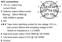
You'll have seen the ACC pin layout/arrangement as seen below in image. I'm not aware of any 'IF' used with this socket/pins.

Can you take a screen shot of this pad labelled IF.


Screenshot (93).png
 

dsalomon

Member
Premium Subscriber
Joined
May 6, 2003
Messages
218
Location
Brooks, GA
Mod done. Works great.

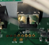
AOR-262 - I was wrong. The pad I was referring to isn't labeled IF, it's "10.7M", and is next to a pad labeled "GND". See attached pic. Not sure which hole corresponds to which pin on the ACC connector.

mspaint_QUhUUclQPO.png

Thanks again for the help!
 

AOR-262

Member
Joined
May 10, 2016
Messages
307
@dsalomon

Something I forget to say also is another method to try, but if you already have made the change that I mention, no worries.

This is another easy method ...

Instead of the 10.7 MHz IF output, you can also try to use 45.05 MHz IF output if the other receiver will accept 45.05 MHz IF.

When 45.05MHz IF will be used, then ALL MODE is supported.

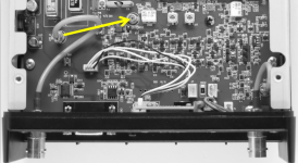
To do this, a coaxial cable needs simply to be unplugged and plugged into another socket, as pictured below (see yellow arrow).

Drawback of this method: Receiver overall sensitivity is reduced by 9dBm, which can be an issue for reception of weak signals. To gain access to the PCB, remove the top cover. Remove the top chassis cover (three screws down each edge of the cover). With the back panel facing you, just unplug and relocate the coaxial cable as pictured below.


Screenshot (97).png
 

dsalomon

Member
Premium Subscriber
Joined
May 6, 2003
Messages
218
Location
Brooks, GA
@dsalomon

Something I forget to say also is another method to try, but if you already have made the change that I mention, no worries.

This is another easy method ...

Instead of the 10.7 MHz IF output, you can also try to use 45.05 MHz IF output if the other receiver will accept 45.05 MHz IF.

When 45.05MHz IF will be used, then ALL MODE is supported.

To do this, a coaxial cable needs simply to be unplugged and plugged into another socket, as pictured below (see yellow arrow).

Drawback of this method: Receiver overall sensitivity is reduced by 9dBm, which can be an issue for reception of weak signals. To gain access to the PCB, remove the top cover. Remove the top chassis cover (three screws down each edge of the cover). With the back panel facing you, just unplug and relocate the coaxial cable as pictured below.


View attachment 169350
Thanks for this. I've already done the mod for the 10.7 and it works fine so I won't change it unless there is an advantage to using the 45MHz tap. Is the bandwidth the same (10MHz)? Does the 10.7MHz tap affect signal levels less than the 45MHz tap? I did see the note about more spurs when the 10.7 is set for all modes, but I haven't really noticed anything...yet.
 

AOR-262

Member
Joined
May 10, 2016
Messages
307
@dsalomon

I have information here but buried deep which I will find. If I remember, the IF Bandwidth is 2 MHz +/- giving a total of 4 MHz Bandwidth. I have no experience of the 45.05 IF. You could be right with the bandwidth @10MHz? Though 10 MHz bandwidth seems high. I cannot remember.
 

dsalomon

Member
Premium Subscriber
Joined
May 6, 2003
Messages
218
Location
Brooks, GA
@dsalomon

I have information here but buried deep which I will find. If I remember, the IF Bandwidth is 2 MHz +/- giving a total of 4 MHz Bandwidth. I have no experience of the 45.05 IF. You could be right with the bandwidth @10MHz? Though 10 MHz bandwidth seems high. I cannot remember.
You're probably right about the 4MHz - I was thinking of another radio. I received a reply from AOR with an manual attachment for the ARD300, which contains the same instructions you sent for both the 10.7 and 45.05 IF modifications. The manual states, as you did, that the 45.05 IF results in the 9dbm signal reduction, but says nothing about that for the 10.7 output, so I assume that means no reduction when using the original connection.
 
Top