ATS 20/20+ Rotary encoder Wrong Direction:
There is really no need to take the soldering iron to your radio when you have one that when you spin the rotary encoder, frequency is in the wrong direction. In your ino sketch two numbers need to be swapped. if 3 is on top change to 2. Change 2 to 3 on the next line

reflash and reset.
Slight lag changing bands:
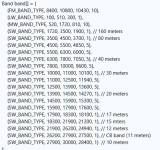
The ino sketch will have two FM and MW lines. Only one of each is needed. Delete the MW and FM band not in your region. This frees up space on the nano which is limited to 32kb. Si4732 doesn't like duplicates like this too.

reflash and reset. ATS 20/20+ will boot with LW band instead of FM.
Note on deleting lines like this. Backspace it up one in alignment to the next line. Never leave spaces between lines in C code!!
Battery Mod without soldering a circuit to the PCB. ATS 20+ ONLY!!
From the factory it is connected to A1 so we need to edit a line. Small change from A2 to A1.

reflash and reset. The older ATS 20 may still need the circuit soldered in but leave it to A2 in the ino sketch.
Fixes tested on firmware 3.0.7g by PU2CLR
In the world of electronics if we do not need to take a soldering iron to a circuit then by all means use the method that works best for. Editing the ino sketch is best.
There is really no need to take the soldering iron to your radio when you have one that when you spin the rotary encoder, frequency is in the wrong direction. In your ino sketch two numbers need to be swapped. if 3 is on top change to 2. Change 2 to 3 on the next line
reflash and reset.
Slight lag changing bands:
The ino sketch will have two FM and MW lines. Only one of each is needed. Delete the MW and FM band not in your region. This frees up space on the nano which is limited to 32kb. Si4732 doesn't like duplicates like this too.
reflash and reset. ATS 20/20+ will boot with LW band instead of FM.
Note on deleting lines like this. Backspace it up one in alignment to the next line. Never leave spaces between lines in C code!!
Battery Mod without soldering a circuit to the PCB. ATS 20+ ONLY!!
From the factory it is connected to A1 so we need to edit a line. Small change from A2 to A1.
reflash and reset. The older ATS 20 may still need the circuit soldered in but leave it to A2 in the ino sketch.
Fixes tested on firmware 3.0.7g by PU2CLR
In the world of electronics if we do not need to take a soldering iron to a circuit then by all means use the method that works best for. Editing the ino sketch is best.
Last edited:


