wgbecks
Active Member
The PPM (Parts Per Million) adjustment is a value you set to trim the SDR device's reference clock (Crystal Oscillator) as a means toDo you want to help me with this too?
compensate for frequency error. In cases of RTL SDR's, it's a bit of trial and error.
Begin by experimenting with the ppm value (-q N) on your rx.py command line (op25.sh). Typically, values; 1, 2, -1, -2 are good places
to begin. Restart op25 each time you change/edit this value and verify that you have trunk signaling blocks (tsbks) count that keeps
incrementing as an indication that op25 is able to decode the control.
Once you've found a ppm value that's close enough to sustain incrementing tsbks, then look at the frequency error reported in the
browser console to determine the extent of the frequency error. Repeat experimentation, if necessary, of the ppm value such that you
maintain tsbks and can reduce reported frequency error to something less that 200 Hz.
IE:
./rx.py --args 'rtl' -N 'LNA:47' -S 1000000 -q 1 -x 2 -T CLMRN.tsv -V -2 -U -l http:0.0.0.0:8080 -v 11 2>stderr.2
./rx.py --args 'rtl' -N 'LNA:47' -S 1000000 -q 2 -x 2 -T CLMRN.tsv -V -2 -U -l http:0.0.0.0:8080 -v 11 2>stderr.2
./rx.py --args 'rtl' -N 'LNA:47' -S 1000000 -q -1 -x 2 -T CLMRN.tsv -V -2 -U -l http:0.0.0.0:8080 -v 11 2>stderr.2
./rx.py --args 'rtl' -N 'LNA:47' -S 1000000 -q -2 -x 2 -T CLMRN.tsv -V -2 -U -l http:0.0.0.0:8080 -v 11 2>stderr.2
RTL SDR's can further be trimmed using (-d N) and (-o N) arguments in addition to ppm (-q N). The first step is
to determine the best ppm value that results in incrementing tsbk count with the least frequency error before
trying to apply additional fine-tuning measures.
As an example, here's what one of my RTL SDR's requires for corrections. -q 1 -o 6500 -d 100
It should be noted that (-o N) offset was intended to relocate a DC spike that some devices have at the center of their tuning spectrum
that can degrade signal demodulation. However, the application of arbitrary offset values in combination with ppm can actually help
to further reduce tuning frequency errors. Every SDR is different in what combinations work best and is the reason that this process
requires trial and error experimentation.
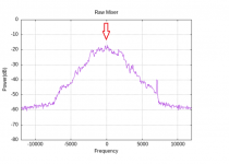
Observation of the mixer plot is very helpful in analyzing tuning error and correction steps provided you are indeed decoding trunk
signaling blocks. The object is to get the center (peak) of control channels spectral plot to align on the center (Zero) frequency scale.


