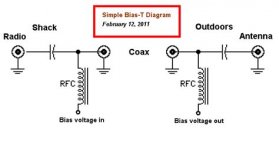
Bad bias tee short?

yellingsoftly

Member
Joined
Mar 22, 2024
Messages
25
Was testing a pair of cheap bias tees like the ones you find on eBay/amazon and so on that others have posted. the first one worked great I can see it’s inserting the proper voltage onto the coax with my multi meter but when I insert the second at the other end of a short coax when testing with the rf+dc port facing away from the antenna towards the other bias tee that is at the receiver I get voltage for a second lower than what’s coming out of the coax but it starts dropping immediately. I’m guessing this tee has a short but thought I would verify I’m using things correctly.

So linear power supply 12 volt 0.5 amp > bias tee with rf + dc port sending power up coax measured at other end of coax at 12 volts > rf+dc port measuring 5 volts at dc port then dropping to near 0 volts after a few seconds of measuring.
 

kruser

Well Known Member
Premium Subscriber
Joined
Nov 25, 2007
Messages
5,049
Location
W St Louis Cnty, MO
Never insert a powered Bias-T with the DC power out end facing the radio. That could destroy the radio's RF input components depending on how it was made. Most radios will have a capacitor in series with the RF signal path that will block external DC from getting into the radio but that's not a given.

For Bias-T's, you only use one on a segment of coax. And you can only supply one voltage source up the coax.
I'm not sure I understand what you're trying to achieve here. From what you said, you are feeding power into two Bias-T's with their DC output sides facing each other.
 

merlin

Active Member
Joined
Jul 3, 2003
Messages
3,030
Location
DN32su
First, only one bias T inserter between the receiver and active device after the antenna (preamp)
as sutch:
Receiver > Bias T inserter > active device > antenna. Some antennas have a DC ground and can short the inserter.
They are diectional and don't work connected backwards. It can damage a receiver.
 

yellingsoftly

Member
Joined
Mar 22, 2024
Messages
25
First, only one bias T inserter between the receiver and active device after the antenna (preamp)
as sutch:
Receiver > Bias T inserter > active device > antenna. Some antennas have a DC ground and can short the inserter.
They are diectional and don't work connected backwards. It can damage a receiver.
I’m trying to extract power from the coax to feed an amp without a built in bias t. I’m only feeding power from the bias t after the receiver. Most of the minicircuits stuff doesn’t have built in bias tee so my understanding was you need two t’s with the one closest to the antenna in reverse to pull power
 

yellingsoftly

Member
Joined
Mar 22, 2024
Messages
25
Never insert a powered Bias-T with the DC power out end facing the radio. That could destroy the radio's RF input components depending on how it was made. Most radios will have a capacitor in series with the RF signal path that will block external DC from getting into the radio but that's not a given.

For Bias-T's, you only use one on a segment of coax. And you can only supply one voltage source up the coax.
I'm not sure I understand what you're trying to achieve here. From what you said, you are feeding power into two Bias-T's with their DC output sides facing each other.
Maybe I did a bad job of explaining it sorry I am only feeding power on the receiving side up the coax. That tests fine 12 volts on the other side of the coax. On the antenna side though I am trying to extract that voltage out to feed a minicircuits amp that doesn’t have a bias tee
 

dlwtrunked

Member
Premium Subscriber
Joined
Dec 19, 2002
Messages
2,348
Maybe I did a bad job of explaining it sorry I am only feeding power on the receiving side up the coax. That tests fine 12 volts on the other side of the coax. On the antenna side though I am trying to extract that voltage out to feed a minicircuits amp that doesn’t have a bias tee

I assumed you were doing that, but some others did not. It is a common thing to try. However, note the bias-T likely has a diode that is in the wrong direction at the far end and in that case needs to be reversed.
 

kruser

Well Known Member
Premium Subscriber
Joined
Nov 25, 2007
Messages
5,049
Location
W St Louis Cnty, MO
Maybe I did a bad job of explaining it sorry I am only feeding power on the receiving side up the coax. That tests fine 12 volts on the other side of the coax. On the antenna side though I am trying to extract that voltage out to feed a minicircuits amp that doesn’t have a bias tee
Gotcha!
I've never used one like this before but I see what you're trying to do.
Can you measure the voltage going into the coax at the first Bias-t near the radio when you attach the 2nd bias tee. It should remain at 12 volts.
One thing comes to mind is a diode inside that 2nd bias tee at the antenna end is preventing the DC from coming back out in reverse of the Tee's purpose. None of my bias tees have a diode but maybe some of those sold on eBay and the likes do?
 

dlwtrunked

Member
Premium Subscriber
Joined
Dec 19, 2002
Messages
2,348
Gotcha!
I've never used one like this before but I see what you're trying to do.
Can you measure the voltage going into the coax at the first Bias-t near the radio when you attach the 2nd bias tee. It should remain at 12 volts.
One thing comes to mind is a diode inside that 2nd bias tee at the antenna end is preventing the DC from coming back out in reverse of the Tee's purpose. None of my bias tees have a diode but maybe some of those sold on eBay and the likes do?
Also, as I think you may be suggesting, when he reverses the bias-T at the other end, it may have a DC-blocking capacitor. I have some that do and some that do not. he needs to tell us more about the bias-T or where he got it from.
 

yellingsoftly

Member
Joined
Mar 22, 2024
Messages
25
Also, as I think you may be suggesting, when he reverses the bias-T at the other end, it may have a DC-blocking capacitor. I have some that do and some that do not. he needs to tell us more about the bias-T or where he got it from.
Ok thanks, this was the one in question but if anyone else has a recommended one that would work better for this propose that’s relatively inexpensive I’m all ears 😊. https://a.co/d/cLg1HKX
 

MUTNAV

Active Member
Premium Subscriber
Joined
Jul 27, 2018
Messages
1,278
Also, as I think you may be suggesting, when he reverses the bias-T at the other end, it may have a DC-blocking capacitor. I have some that do and some that do not. he needs to tell us more about the bias-T or where he got it from.
I was just about to mention a capacitor, I was typing while your reply came up.

This is what I imagine when someone mentions a bias T for power and RF at the same time. No diodes. Just caps (at least the important components).

Thanks
Joel
1717958571035.jpeg
 

kruser

Well Known Member
Premium Subscriber
Joined
Nov 25, 2007
Messages
5,049
Location
W St Louis Cnty, MO
Also, as I think you may be suggesting, when he reverses the bias-T at the other end, it may have a DC-blocking capacitor. I have some that do and some that do not. he needs to tell us more about the bias-T or where he got it from.
No, I was basically talking about the same possible diode as you mention in your post. That pretty much has to be why no positive DC is available at the 2nd Bias-T. My question about the voltage level was to rule out a short in the 2nd bias-T when the op said the voltage dropped from 5 to zero quickly. That stray voltage probably was from a filter cap for the power side of the T.

In most cases, you'd want the DC Blocking cap unless you still need to power another device even closer to the antenna. Now that I've never seen is a bias-T without a DC blocking cap.
 

yellingsoftly

Member
Joined
Mar 22, 2024
Messages
25
I was just about to mention a capacitor, I was typing while your reply came up.

This is what I imagine when someone mentions a bias T for power and RF at the same time. No diodes. Just caps (at least the important components).

Thanks
Joel
View attachment 163675
Yah that’s exactly what I’m trying to do. Suppose I could build the circuit but seemed like something I could get easily since there’s lot of inexpensive bias tees. Guess I’m not sure what I’m looking for as far as identifying tees without that diode mentioned.
 

kruser

Well Known Member
Premium Subscriber
Joined
Nov 25, 2007
Messages
5,049
Location
W St Louis Cnty, MO
Ok thanks, this was the one in question but if anyone else has a recommended one that would work better for this propose that’s relatively inexpensive I’m all ears 😊. https://a.co/d/cLg1HKX
Unless the diagram shown in the image is wrong, this model has no reverse voltage diode in it that would block power from coming back out.
Chances are, the drawing is wrong in the images.
 

MUTNAV

Active Member
Premium Subscriber
Joined
Jul 27, 2018
Messages
1,278
Unless the diagram shown in the image is wrong, this model has no reverse voltage diode in it that would block power from coming back out.
Chances are, the drawing is wrong in the images.


Pretty sure I'm not wrong,

I'm open to learning new things though, so let me know of some other applications of a diode in an RF bias T

I'm still trying to figure out why someone would need a diode in a bias T to begin with, except for some fancy arrangement like Ramsey kits SM-100, that ran RF, powered the antenna mounted amplifier, AND provided a variable voltage for a tuning diode at the antenna. over a single RF cable.


At 5:32 he takes apart the smaller of the two he's showing, and identifies the components.

another option is to do a yahoo search for RF bias T and select images.

dwtrunked may be correct, if the bias t is reversed at the antenna side, the blocking cap is on the wrong side and could give you the reading your getting.

Thanks
Joel
 
Last edited:

prcguy

Member
Premium Subscriber
Joined
Jun 30, 2006
Messages
16,055
Location
So Cal - Richardson, TX - Tewksbury, MA
Unless the diagram shown in the image is wrong, this model has no reverse voltage diode in it that would block power from coming back out.
Chances are, the drawing is wrong in the images.
I’ve never seen a bias T with a diode, you should be able to run a positive or negative voltage through them unless it’s made for a specific purpose.
 

dlwtrunked

Member
Premium Subscriber
Joined
Dec 19, 2002
Messages
2,348
I’ve never seen a bias T with a diode, you should be able to run a positive or negative voltage through them unless it’s made for a specific purpose.
I have. One I got from now gone Wellbrook for their active loop.
 

dlwtrunked

Member
Premium Subscriber
Joined
Dec 19, 2002
Messages
2,348
Unless the diagram shown in the image is wrong, this model has no reverse voltage diode in it that would block power from coming back out.
Chances are, the drawing is wrong in the images.
I bet the diagrams is right (and there is no diode). And he needs to make sure the capacitor end faces the radio on the radio end of the coax and that the capacitor faces the antenna on the antenna end of the coax.
 

yellingsoftly

Member
Joined
Mar 22, 2024
Messages
25
So not sure if one of the bias tees was just bad but I got a couple more to test yesterday and it acted the same until I replaced the one on the receiver end. Replaced it with another in the same orientation and everything worked.really appreciate everyone chiming in I was confused since I hadn’t done this before
 
Top