Ubbe
Member
I sweept the antenna input of my BCD536HP to look at the impedance and filter characteristics.
It seems to be 7 filters, some are 2-pole and others 3-pole. Component tolerences are probably 5% at best so at 400MHz it could be a +/-20MHz difference between different BCD536HP scanners.
Some people are concerned about impedance matches of antenna-coax-scanner and advocate only to use 50 ohm coax but there's no reason for it. A discone or logperiodic antenna could have somewhat constant impedance in it's designed frequency range but not other types of antennas. And a scanners filters are not of a such an expensive and complex designed that it can hold 50 ohm impedance over any larger part of its range.
First column is the frequency range and the second one are 2 or 3 frequencies that states the tuned frequencies of the filter and third column are some examples of usually the min and max impedance values within the filters frequency range. I used an inexpensive miniVNATiny analyzer so it might not be a 100% exact result.
25-50MHz 30MHz 55MHz 60ohm@32MHz 15@42MHz 30@52MHz
50-107MHz 72MHz 115MHz 30ohm@50MHz 100@60MHz 22@75MHz 85@87MHz
108-136MHz 120MHz 150MHz 30ohm@118MHz 100@130MHz 15@165MHz 145@185MHz
137-240MHz 138MHz 215MHz 40ohm@137MHz 110@150MHz 14@180MHz
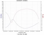
240-330MHz 210MHz 320MHz 100ohm@240MHz 23@265MHz 95@290MHz 36@310MHz 60@325MHz
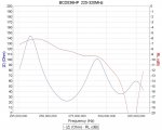
330-512MHz 300MHz 370MHz 485MHz 50ohm@330MHz 25@345MHz 55@370MHz 22@400MHz 155@445MHz 33@480MHz 100@510MHz
760-1300MHz 750MHz 950MHz 1250MHz 35ohm@760MHz 110@800MHz 20@850MHz 50@1250MHz
/Ubbe
It seems to be 7 filters, some are 2-pole and others 3-pole. Component tolerences are probably 5% at best so at 400MHz it could be a +/-20MHz difference between different BCD536HP scanners.
Some people are concerned about impedance matches of antenna-coax-scanner and advocate only to use 50 ohm coax but there's no reason for it. A discone or logperiodic antenna could have somewhat constant impedance in it's designed frequency range but not other types of antennas. And a scanners filters are not of a such an expensive and complex designed that it can hold 50 ohm impedance over any larger part of its range.
First column is the frequency range and the second one are 2 or 3 frequencies that states the tuned frequencies of the filter and third column are some examples of usually the min and max impedance values within the filters frequency range. I used an inexpensive miniVNATiny analyzer so it might not be a 100% exact result.
25-50MHz 30MHz 55MHz 60ohm@32MHz 15@42MHz 30@52MHz
50-107MHz 72MHz 115MHz 30ohm@50MHz 100@60MHz 22@75MHz 85@87MHz
108-136MHz 120MHz 150MHz 30ohm@118MHz 100@130MHz 15@165MHz 145@185MHz
137-240MHz 138MHz 215MHz 40ohm@137MHz 110@150MHz 14@180MHz
240-330MHz 210MHz 320MHz 100ohm@240MHz 23@265MHz 95@290MHz 36@310MHz 60@325MHz
330-512MHz 300MHz 370MHz 485MHz 50ohm@330MHz 25@345MHz 55@370MHz 22@400MHz 155@445MHz 33@480MHz 100@510MHz
760-1300MHz 750MHz 950MHz 1250MHz 35ohm@760MHz 110@800MHz 20@850MHz 50@1250MHz
/Ubbe