DIY 4-port Active Multicoupler

aaknitt

Member
Feed Provider
Joined
Aug 27, 2005
Messages
1,300
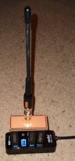
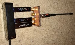
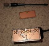
Here's a 4-port active multicoupler that I put together.
PCB.jpg Top.jpg Side.jpg

The intended use case is to feed a bank of four RTL-SDR dongles plugged into a USB hub with a single antenna, but it can be used for other purposes as well. It can get power from one of the RTL-SDRs equipped with an internal bias tee or from external regulated 3 to 5 VDC. The SMA males connecting directly to the SDRs can easily be substituted with SMA females if cable connections are desired instead.

Design files and more details are here if anyone wants to make their own.

I just got the first prototype PCB assembled today and it seems to be performing about as expected, but I haven't taken any measurements with real test equipment yet.

Cost to build a single prototype was about $35 for parts, circuit boards, and shipping. I think I could get that down to $10 or $15 buying parts in larger quantities. If anyone is interested in participating in a bulk purchase, let me know what you'd be interested in:
  • Fully assembled unit
  • PCB only
  • PCB and SMD + SMA connectors parts kit
  • PCB and SMD only parts kit
  • What gender SMA connector(s)
Andy
 

prcguy

Member
Joined
Jun 30, 2006
Messages
15,384
Location
So Cal - Richardson, TX - Tewksbury, MA
I have a few questions after looking over the schematic. Do you have any slope compensation for the amplifier that has 7dB more gain @50MHz than at 1GHz? Maybe replace C1 with something in the 2-4pf range which will roll off low frequency gain?

I see the amplifier chosen has an IP1 of less than 20dBm and IP3 around 33dBm, both pretty low and can contribute to overloading in many users areas due to high RF environments. Those are specs at 5V and they are worse at 3V. Have you considered a higher IP1/IP3 amplifier? Its also better to choose an amplifier with just enough gain to overcome splitter losses which should be around 6-7dB for a 4-way and 9-10dB for an 8-way. Excessive gain can push the amplifier into IMD land earlier for no good reason.

I saw some questions on the github site and one was about symmetry in the PCB splitter legs. This is because they are usually a Wilkinson power divider and the traces are a specific length in fractions of a wavelength and not 50 ohms. For example a two way divider would have two stripline traces that are roughly 75 ohms each and 1/4 wavelength long each then bridged at the output side with a 100 ohm resistor. 4-way and 8-way would have progressively higher impedance stripline traces. This arrangement provides good isolation between ports and requires only one attenuator at the divider input for gain adjustment. You don't usually see 50 ohm striplines going to individual attenuators at each output in a power divider.

The lengths of the striplines also affect the phase of each signal at the output ports of the divider with longer traces in some paths causing more phase change in those paths. Ideally whatever comes out of the divider will be at the same phase at all ports.
 
Last edited:

aaknitt

Member
Feed Provider
Joined
Aug 27, 2005
Messages
1,300
I have a few questions after looking over the schematic. Do you have any slope compensation for the amplifier that has 7dB more gain @50MHz than at 1GHz? Maybe replace C1 with something in the 2-4pf range which will roll off low frequency gain?

I see the amplifier chosen has an IP1 of less than 20dBm and IP3 around 33dBm, both pretty low and can contribute to overloading in many areas. These are specs at 5V and they are worse at 3V. Have you considered a higher IP1/IP3 amplifier?
All good questions. And pretty much the answer to all of them is "not really, it's good enough for what I need it for". It's probably on par with a cheap powered CATV amp but more convenient due to lack of cables and adapters, but probably not as good as a Stridsberg or something that's been highly engineered. This is targeting low cost rather than high performance.
For general scanning use, flat gain across a wide bandwidth isn't really critical (at least for what I'd be using it for). All I'm trying to do is overcome the loss of the splitting. With that being said, I think the LNA I based this on was using 4.7 pF for C1 and C3 probably for that very reason, so it may make sense to switch those values.

If there's a different amp you'd recommend that has the IP1/IP3 you're looking for, I can check the footprint to see if there's a way to make it work with both the existing one and a different one so people could drop in the "cheap" or "performance" IC depending on their needs.
 

prcguy

Member
Joined
Jun 30, 2006
Messages
15,384
Location
So Cal - Richardson, TX - Tewksbury, MA
All good questions. And pretty much the answer to all of them is "not really, it's good enough for what I need it for". It's probably on par with a cheap powered CATV amp but more convenient due to lack of cables and adapters, but probably not as good as a Stridsberg or something that's been highly engineered. This is targeting low cost rather than high performance.
For general scanning use, flat gain across a wide bandwidth isn't really critical (at least for what I'd be using it for). All I'm trying to do is overcome the loss of the splitting. With that being said, I think the LNA I based this on was using 4.7 pF for C1 and C3 probably for that very reason, so it may make sense to switch those values.

If there's a different amp you'd recommend that has the IP1/IP3 you're looking for, I can check the footprint to see if there's a way to make it work with both the existing one and a different one so people could drop in the "cheap" or "performance" IC depending on their needs.
I updated my post with more info since your post above. Are you using something like a spice circuit simulator program to see how things behave? If so you should be able to change the value of C1 then run it at say 100MHz and 1GHz to find the desired roll off effect.

I can look around to see if there is a more suitable amp chip.
 

aaknitt

Member
Feed Provider
Joined
Aug 27, 2005
Messages
1,300
Its also better to choose an amplifier with just enough gain to overcome splitter losses which should be around 6-7dB for a 4-way and 9-10dB for an 8-way. Excessive gain can push the amplifier into IMD land earlier for no good reason.

Aren't those values for a Wilkinson though? Doesn't a resistive splitter like this have 3 dB additional loss per split, so this four port has 12 dB loss? Even with that loss though, I agree that this has a bit more gain that it should. I was going to add an additional Pi attenuator but decided against it to save space.

The lengths of the striplines also affect the phase of each signal at the output ports of the divider with longer traces in some paths causing more phase change in those paths. Ideally whatever comes out of the divider will be at the same phase at all ports.

I was thinking that for this resistive type of divider it really would only impact phase. And for this type of scanning application, does that even matter? I could probably save some space and shrink this thing down a bit if I didn't care about equal phase at the outputs.
 

Ubbe

Member
Joined
Sep 8, 2006
Messages
9,055
Location
Stockholm, Sweden
Maybe a separate amplifier and a standard CATV splitter that has 20dB isolation between ports would have been a better solution using a suitable attenuation before the splitter. $17 for a PGA103+ amplifier and $10 for a splitter and then a fixed $5 attenuator would give a much higher performance, even compared to a Stridsberg, and would be much more flexible to adapt for other use at the same cost and less hassle than to build it yourself. But it's fun with DIY even if isn't any improvement over a standard solution.

/Ubbe
 
Top