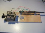
Homebrew DIY AM ferrite antenna, variable capacitor configuration

Status
Not open for further replies.

PaulQ

Member
Joined
Mar 19, 2021
Messages
28
Location
Maine, US
Thanks Forum community for opportunity to post, first time.
My eventual goal is to use this antenna in a DIY MW/LW receiver project, with the TA 7642 AM radio IC.

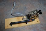
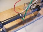
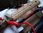
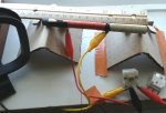
This is my first DIY antenna, 120 turns of 28 AWG enameled copper wire, on a 135 x 10mm ferrite bar. The twisted antenna wires get plugged in to external AM antenna jack on stereo. Without the variable capacitor (141.6 pF yellow lead, black lead ground to copper baseboard water pipe, red lead 59.2 pF), I barely get signal. With the variable capacitor configuration, the antenna's performance is much better, but half that of the cheap, 5", 8-loop coil AM antenna (left). Performance is the same switching yellow and red leads. The signal is best across the spectrum when the capacitor tuning knob is fully counter-clockwise. The extra capacitor is to show you the back.

My goal in getting this large ferrite bar is to make a MW/LW beast with impressive reception. So thanks in advance for guidance.
Ferrite2.jpg
 
Last edited:

prcguy

Member
Premium Subscriber
Joined
Jun 30, 2006
Messages
16,263
Location
So Cal - Richardson, TX - Tewksbury, MA
I recently made a tunable ferrite antenna also and its working far beyond my expectations. I ran across a Youtube video of a guy making them with 16" long ferrite rods. His plans are easy and you can use the antenna near an AM radio with built in antenna to improve its reception or connect a coupling loop to feed antenna input terminals on radios that can use external antennas. The video also explains the exact amount of measurable inductance you need to wind so a 365pf variable capacitor will cover the entire AM broadcast band and there is another version that uses a variable cap and switched fixed caps to cover a range from AM broadcast to about 4Mhz.

Check out my post #85 in this thread, there is a link to the video that inspired me to build one and the bottom picture is the first run of the prototype I built. Portable radio AM dxing

My ferrite rod has a 365pf variable attached to it and the frequency range is about 500KHz to 2MHz. The loop not only rotates in its mount but tilts to get the final few dB of null when needed.
 

majoco

Stirrer
Joined
Dec 25, 2008
Messages
4,315
Location
New Zealand
Here's a pic of one I used on an AM tuner that had no internal antenna.....

Ferrite tuner.jpg

I can't find it at the moment, but I have found a ferrite rod with windings on it. It appears to have about 50 turns on it connected to the tuning capacitor and another winding of about 5 turns for coupling to the radio. If I find the pictured one I'll do some more investigation. I do recall that it worked very well.
 

PaulQ

Member
Joined
Mar 19, 2021
Messages
28
Location
Maine, US
Here's a pic of one I used on an AM tuner that had no internal antenna.....

View attachment 100812

I can't find it at the moment, but I have found a ferrite rod with windings on it. It appears to have about 50 turns on it connected to the tuning capacitor and another winding of about 5 turns for coupling to the radio. If I find the pictured one I'll do some more investigation. I do recall that it worked very well.
Thanks for this Martin. Wow 50 turns. My goal is to receive MW and LW signals, so I should keep 100+ turns on the bar. I can't see the 5-turn coupled section. How far to separate that from primary winding? And any intel about my capacitor configuration would be appreciated as it looks different from your air capacitor. Thanks again.
 

prcguy

Member
Premium Subscriber
Joined
Jun 30, 2006
Messages
16,263
Location
So Cal - Richardson, TX - Tewksbury, MA
The higher in frequency you go the less turns you need on the ferrite. To cover a wide range you would wind the ferrite to resonate at the higher frequencies with minimal capacitance then use a variable 0-365-pf capacitor for tuning then switch in fixed capacitors to lower the tuning range of the ferrite. The problem is a variable capacitor will only cover a certain range and not enough to resonate the ferrite coil much more than the range of the AM broadcast band or a similar percentage at higher frequencies. I have come across 50-1600pf variable caps but tuning would be extremely critical and they are huge.

You also need a way to measure the inductance of the windings on your ferrite. There are on line calculators for capacitor and inductor resonance and they work perfectly for setting up a ferrite rod antenna. You simply pick the lower frequency you want to use, enter the maximum capacitance of your variable cap and it will tell you how much inductance you need to resonate at the low end of your setup. Then enter that inductance and minimum capacitance you have and it will tell you the high end tuning of your setup.

For tuning the AM broadcast band 540KHz to 1.8MHz range and using the industry standard 0-365pf variable capacitor, you would want to wind enough wire on the ferrite to reach about 280 microhenries. To tune up to about 4MHz you would need about 82 microhenries, but you can add fixed capacitors across the variable and tune that down to the AM broadcast band for a really wide tuning antenna. The key to all this is being able to accurately wind the wires on the ferrite to the needed amount of inductance.

Without an inductance meter you can use an SDR receiver or one with a spectral display, wind your ferrite and add the tuning cap then see were you have a noise peak as you tune it around. If its too low in frequency take some windings off and if it resonates too high in frequency add some windings, etc. Every ferrite rod will take a different number of windings for a given amount of inductance so unless you are following someone else's build it instructions and have the exact same ferrite you will need an inductance meter or an SDR to measure the end result.

Thanks for this Martin. Wow 50 turns. My goal is to receive MW and LW signals, so I should keep 100+ turns on the bar. I can't see the 5-turn coupled section. How far to separate that from primary winding? And any intel about my capacitor configuration would be appreciated as it looks different from your air capacitor. Thanks again.
 

WA8ZTZ

Member
Joined
Feb 23, 2014
Messages
1,016
Location
S.E. MI
Hi Paul, welcome aboard.

You have actually taken on two projects here.
One is the AM radio on a chip and the other is the ferrite antenna.
Have tinkered with the TA7642 here with limited success. Got it to work but
never had a lot of luck with it as a DX machine.

Otherwise, regarding the ferrite rod loopstick, what type of material are you using?
Have had good luck here with type 61. Other guys have had success with types
43, 73, 75, and J. A lot of this work is cut and try. There are published formulas
for turns count and inductance and capacitance values but in the end you will have
to fine tune them by experimentation. My advice would be to increase the number
of turns on your bar to at least 150 or a bit more. Be sure to have a good ground.
Performance without a ground will suffer.
 

majoco

Stirrer
Joined
Dec 25, 2008
Messages
4,315
Location
New Zealand
I suspect that in your variable capacitor there are two separate parts - one to tune the antenna and on to tune the oscillator. Forget about the oscillator - if you can see inside the capacitor it will be the smaller of the two. I guess the centre terminal will be the common for both of them.
You need to connect the common - your black lead - to one end of the winding and one of the outer two connections to the other end of the winding. That's all - no connection to the radio. Bring another AM band radio close to the ferrite antenna and tune it to a station at the low frequency end of the AM BC band. Now slowly turn the ferrite rod capacitor through it's range and see if you get a peak in the signal. If the signal is getting stronger but you get to the end of the capacitor, then you have too many turns. (Personally I would have made a test winding with a tap every ten turns or so.) You could try on the LW band (if you are in Europe?) but there's not much anywhere else in the world!

Loops.jpg3-gang cap.jpg

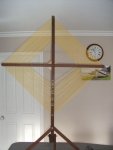
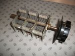
Here's a pic of a loop antenna and a 3-gang capacitor I made to tune ferom about 200kHz up to 1700kHz by using taps on the winding and all the gangs of the capacitor - worked well for the AM BC band but still not enough windings for the LW band with all three gangs.

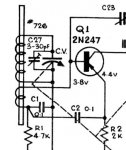
Here's a schematic of the antenna in a one-band AM radio. You can see the main winding is only connected to the tuning capacitor - forget the trimmer cap - and a separate small winding goes to the base of the transistor.

Ferrite antenna.jpg
 

KB4MSZ

Billy
Premium Subscriber
Joined
Mar 12, 2018
Messages
972
Location
Tampa, Florida
I envy you guys who can DX with the AM broadcast band. In Tampa, I do everything I can to GET RID of it.
:(
 

majoco

Stirrer
Joined
Dec 25, 2008
Messages
4,315
Location
New Zealand
Well, I found the original but unfortunately something hard and heavy had fallen onto the rod and smashed it. I refitted the newer one I found in the junk box and it seems to work just as well. Don't criticise the soldering - the wires were just tacked on! At the LF end it brings up a station on 567 kHz that was barely audible on a Degen 1103 receiver and similarly at the HF end on 1548kHz at 4pm - just sitting on the bench in my playroom under a steel roof. I didn't tune the inductance but that is done by sliding the coil along the rod until you find the sweet spot where the LF end coverage is just right. I think the capacitor is just a standard 10 to 365pF job for a AM band radio

DSCF1505.JPG

In this pic you can see the red and black leads going to one gang of the tuning capacitor and the green and white going to the terminal block.

DSCF1507.JPG

Here you can see the terminations on the coils. The black and red leads are the whole of the larger coil, the green and white are connected to the small coil on the end of the cardboard tube.
 
Last edited:

PaulQ

Member
Joined
Mar 19, 2021
Messages
28
Location
Maine, US
Thanks so much majoco, I'll implement your suggestions and report back soon.
Thanks others as well for helpful responses.
 

merlin

Active Member
Joined
Jul 3, 2003
Messages
3,090
Location
DN32su
I got a new birthday toy that could help you tune or even design your own antenna.
The NanoVNA-H4, under $100, very worth it for any antenna projects to 900Mhz.
 

majoco

Stirrer
Joined
Dec 25, 2008
Messages
4,315
Location
New Zealand
Going right back to about post #6, McKenna said:
To cover a wide range you would wind the ferrite to resonate at the higher frequencies with minimal capacitance then use a variable 0-365-pf capacitor for tuning then switch in fixed capacitors to lower the tuning range of the ferrite.

I tried to bring down the frequency range of my big loop by adding fixed capacitance but it has an undesirable effect - I hope I can explain it well enough. The resonant frequency of any L/C parallel circuit is given by: freq = 1/(2pi x (sqr rt(L x C))). Now the only variable is the capacitor so we can say that the resonant frequency varies inversely as the square root of the capacitance. The old fashioned air spaced capacitors had a range of about 50 to 450pF for a reason - the AM broadcast band goes from around 540 khz to 1620kHz, a ratio of about 3 to 1, the capacitor has a ratio of about 450/50 = 9 and the square root of 9 is 3! Magic - with a capacitor of 50 to 450 pf we can tune from 540 to 1620kHz with an inductor of 220uH. (Resonant Frequency Calculator for LC Circuit) The newer capacitors like those plastic cubes have a different dielectric and so have a range from 35 to 365pf but the ratio is the same - just need a different coil.

NOW - suppose as we want to cover a lower frequency range, we added a fixed capacitor in parallel with our variable - pick one about the same as the maximum value of the variable, say 425pf. Working backwards from the formula, the inductor has a value of about 220uh. Now we have a range of 475 to 875pf on our modified capacitor, and so our highest frequency will now be 490kHz, almost the same as the lowest before as we would expect - but the new low frequency has gone down to only 363kHz, not the 490/3 = 160kHz we were hoping for. This is because the ratio of max to min of the tuning cap is now only 1.8:1, not the 9:1 we had previously.

The only way around this is to add another variable capacitor like the one in my pic. This came from an old radio with an RF amplifier as well as the usual antenna tuner and oscillator tuner. The minimum capacitance of all three in parallel was still low-ish at just over 150pf and the maximum was about 1350pf but I still couldn't get down to below 200kHz which was where I wanted to go. As you can see from the pic, my loop was full!
 
Last edited:

PaulQ

Member
Joined
Mar 19, 2021
Messages
28
Location
Maine, US
Thanks majoco, this helps me understand the inverse relationship of capacitance to frequency, and how a fixed capacitor reduces the tuning capacitor's ratio. How will you be able to get below 200kHz?
 

majoco

Stirrer
Joined
Dec 25, 2008
Messages
4,315
Location
New Zealand
More wire, more turns, more inductance! But you get to the law of diminishing returns,, just like the capacitor. Sometimes you just can't win!
 

PaulQ

Member
Joined
Mar 19, 2021
Messages
28
Location
Maine, US
I've implemented suggestions and the variable capacitor is working. The twisted leads from the coupling coil (8 turns, far right) are soldered to portable radio circuit board (I removed original loopstick). Black jumper cables (middle of capacitor and far end of primary coil) go to ground (water pipe), red cable connects OSC and ANT on capacitor, and primary winding (120 turns) is connected to ANT. When tuning counterclockwise (towards 141.6 pf pin), lower frequencies get noticeably louder; when turning clockwise (towards 59.2 pf), higher frequencies are improved. So that indicates capacitance as inverse to frequency. The overall signal isn't appreciably better than the 50mm original loopstick. Thanks in advance for improving performance.
AM ANT 2.jpg
 

PaulQ

Member
Joined
Mar 19, 2021
Messages
28
Location
Maine, US
How to edit post please?
The signal is clearer after removing red cable connecting ANT and OSC on capacitor.
The ground connection (heater water pipe) doesn't seem to help signal much.
Suggestions for MW improvement are appreciated. As mentioned in first post I'd also like to receive LW signals. My portable radio scans 153 - 279 kHz, but I haven't yet received those stations with either original loopstick or my DIY in picture. Why might I be receiving shortwave stations (whip antenna) over greater distance than MW/LW stations? I thought longer wavelengths travel further. Thanks.
 

prcguy

Member
Premium Subscriber
Joined
Jun 30, 2006
Messages
16,263
Location
So Cal - Richardson, TX - Tewksbury, MA
I believe winding the coupling loop over the center of the primary winding will give the best coupling and you want to use the least amount of turns in the coupling loop to give satisfactory signal level, which will also give the highest Q or narrowest band width at resonance. Four turns might be a good starting value for the coupling loop.
 

majoco

Stirrer
Joined
Dec 25, 2008
Messages
4,315
Location
New Zealand
There aren't many longwave stations left and with your location you should be listening for the European/African stations in your evening and also note that the ferrite antenna is very directional.
Longwave and medium wave broadcasts cover their intended listeners by the groundwave which in theory only travels a few wavelengths. There are very low frequency transmitters right down to 11kHz which may/will travel worldwide. Shortwave station broadcasts are reflected from ionised layers in the upper atmosphere and are heard over a great distance - there is still a ground wave but quite short and there is a "dead zone" between the end of the ground wave and the first return.
That being said - I have heard a carrier on 198kHz but no modulation to confirm what is was - maybe a birdie.
 
Last edited:

PaulQ

Member
Joined
Mar 19, 2021
Messages
28
Location
Maine, US
I believe winding the coupling loop over the center of the primary winding will give the best coupling and you want to use the least amount of turns in the coupling loop to give satisfactory signal level, which will also give the highest Q or narrowest band width at resonance. Four turns might be a good starting value for the coupling loop.
Thanks for responding. I experimented with 4 to 8 turns around center of primary coil, trying both widely and tightly spaced loops; either way reception is poor as compared to separate coupling loop in last picture.

Thanks majoco for the follow-up about ground waves.
 

majoco

Stirrer
Joined
Dec 25, 2008
Messages
4,315
Location
New Zealand
It sounds like you are not covering the AM broadcast band properly yet. The figures you give for the variable capacitor sound really strange - how did you measure them? The antenna capacitor should have a range of say 35 to 365 pF when connected across your coil of about 220uH. When you tune the capacitor to the low frequency end of the band, a signal about 600kHz should peak and then reduce before you get to the physical end of the capacitor - the same at the high frequency end - a signal at 1550 khz should peak and then reduce before the end again. I still think you have far too many turns on the tuning coil on the rod - five turn on the coupling coil sounds about right. Here's a bit of light reading for you....


Sunday tomorrow, I might have a play with another naked rod and some wire..... :rolleyes:
 
Status
Not open for further replies.
Top