EFHW antenna grounding

APTN_Chewie

Newbie
Joined
Dec 13, 2022
Messages
4
Hi All -

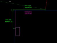
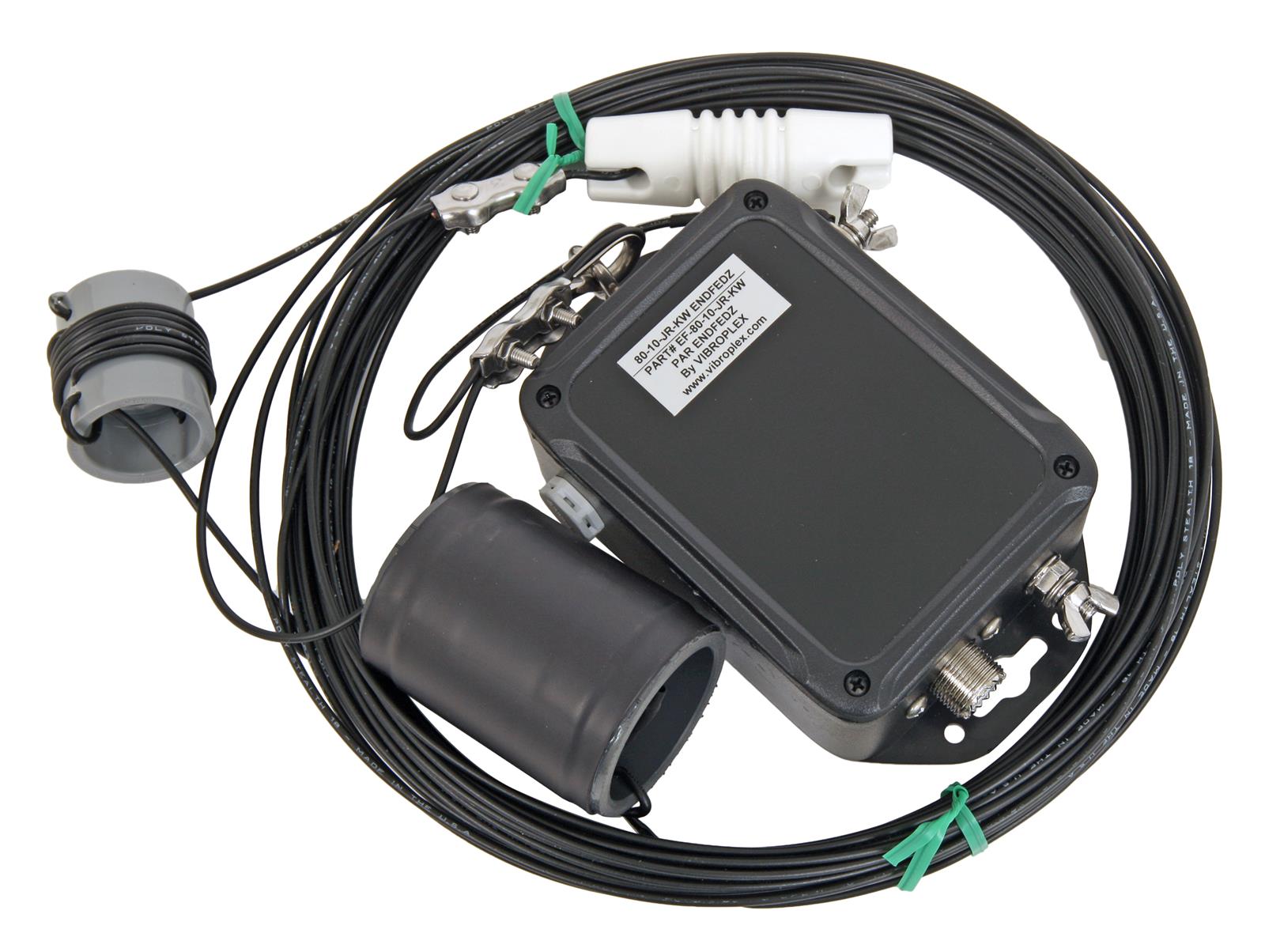
I'm new to ham (have my general), but haven't even been on the air yet. I want to get started with an 8010 efhw from DXengineering. I want to run it from the peak of my shop (metal pole barn) on a mast about 30 feet above ground and 10 foot (approx) above the shop roof) to the peak of my house (about 20' above ground). A couple of questions for the group...

1. The antenna is 74 feet long. About 20' of that will be over a metal roof. I was going to put a 10' mast on the back of the shop to get the antenna above the roof. will this work or am I being dumb and need to look for another solution?

2. The antenna has an impedance transformer, which I need to ground. If I run a roughly 20' ground wire, for the antenna, and a 10' ground for the shack does that look ok? I can move the ground closer to the shack if that is better, but results in a longer antenna ground.

I may be very well over thinking this (I am an engineer), but trying to set myself up with the best chance of success. My rig will be a kenwood TS820 and a TS520 if that makes any difference to my setup.

Thanks in advance for the help.


antena_radio setup overview.jpg


antena_radio setup detail.jpg


J
 

prcguy

Member
Premium Subscriber
Joined
Jun 30, 2006
Messages
16,326
Location
So Cal - Richardson, TX - Tewksbury, MA
What make and model is the antenna? If its 74ft long it doesn't sound like an EFHW, which is a resonant antenna operated on harmonically related bands. If its simply an end fed with non resonant length wire then the coax is the counterpoise for the antenna and you would a good common mode choke in the feedline near the shack to strip RF off the coax. If you have not purchased an antenna yet I might recommend MyAntennas for a resonant end fed, they are the best quality I have found and made by an actual antenna engineer and not in some garage.

For grounding, unless the mfr says to specifically ground the transformer, the NEC says you can ground the shield of the coax along the line and its good to do that near where the coax enters the building. Legally you would want to ground that to your AC entry panel ground.

As for the antenna being over a metal roof for 20ft, that will impact its radiation pattern and it would have to be modeled to know the exact consequences. I think raising it higher above the metal roof is going in the right direction. Being mostly 30ft above ground is very good in my opinion giving mostly straight up radiation (NVIS) on lower bands like 80 and 40m then on 20 and 10m you should get some low angle take off for better DX. Not that the antenna will not work DX on 80 or 40m, I have a 133ft OCFD at about 30-35ft and can talk coast to coast in the evenings on 80 and 40m.
 

APTN_Chewie

Newbie
Joined
Dec 13, 2022
Messages
4
Sorry, I should have posted the antenna -


I'll check out the MYantennas as well.

Its funny, when studying for the tech/general, I was thinking, this isn't that hard. Now that I'm actually doing the application, I realize I don't know a bloody thing... LOL

Again, thanks for the help!
 

krokus

Member
Premium Subscriber
Joined
Jun 9, 2006
Messages
6,128
Location
Southeastern Michigan
Using metal poles to support the antenna give another consideration item: a non-conductive support between the antenna and the poles. Generically, the longer the better, but at least a couple feet.
 

Dirk_SDR

Member
Joined
Jan 3, 2022
Messages
323
Location
Germany
Hi All -

...
2. The antenna has an impedance transformer, which I need to ground. If I run a roughly 20' ground wire, for the antenna, and a 10' ground for the shack does that look ok? I can move the ground closer to the shack if that is better, but results in a longer antenna ground.
2. Every way to shorten the RF-ground connection to the shack and also to the antenna is good. If you have a way to use a short ground for the antenna and another short way for the shack (that means 2 ground poles!), I would use that option. The 2 ground poles must then be connected directly e.g. with an earth cable.
Another option would be to test a counterpoise (1/4 Lambda) as antenna ground.
 

merlin

Active Member
Joined
Jul 3, 2003
Messages
3,094
Location
DN32su
You should only ground the transformer/balun at its ground point. what ever length the ground is to earth will act as counterpoise and consider that. Shorter is better. No part of the long wire itself should be grounded. Your mast at the far end, use an insulator at the support.
74 foot horizontal should give good performance 10 to 80 meters.
Sorry, I should have posted the antenna -


I'll check out the MYantennas as well.

Its funny, when studying for the tech/general, I was thinking, this isn't that hard. Now that I'm actually doing the application, I realize I don't know a bloody thing... LOL

Again, thanks for the help!
Real world isn't always by the book, but don't over complicate things, its not.
 

prcguy

Member
Premium Subscriber
Joined
Jun 30, 2006
Messages
16,326
Location
So Cal - Richardson, TX - Tewksbury, MA
This specific PAR end fed antenna does not require any grounding for use and grounding of any type would only be to appease the National Electrical Code for human safety. For that you can ground the coax shield near where it enters the building. I would also use a good ferrite based RF choke or 1:1 balun somewhere in the feedline before the grounding point.
 

APTN_Chewie

Newbie
Joined
Dec 13, 2022
Messages
4
Thanks for the replies guys. I got everything run into the house and hooked up a mobile 10m radio up. Unfortunately, my results were disappointing. I got nothing but static on the entire band. I've got a kenwood TS520 and a 820S also, but I have no clue how to use these radios yet so all I did was basically turn them on to see if they fired up. All my equipment was purchased 2nd hand from a friend of my wife. The operator passed and his wife didn't know anything about the equipment. When we bought it, we didn't know anything either :) so I don't know if these radios even work. I know the digital display on the 820 isn't working as it shows a 0 for the frequency. I don't know if that is a display issue or a VFO issue.

I probably need an antenna tuner and maybe a little more modern radio, just to get my feet wet and put these older rigs back on the bench for later.
 

K6GBW

Member
Joined
May 29, 2016
Messages
640
Location
Montebello, CA
That particular antenna really is for lower bands like 80-40-20 meters. It's also meant to be used with an external antenna tuner. It will tune up on 10 meters with a tuner, but it will have a lot of lobes on the shorter wavelengths. For 10 meters it's really hard to beat something like an Antronn A99 CB antenna.
 

AC9KH

Member
Joined
Nov 5, 2014
Messages
120
Location
Northern Wisconsin
Hi All -

I'm new to ham (have my general), but haven't even been on the air yet. I want to get started with an 8010 efhw from DXengineering.

I don't know why they would call that antenna a EFHW. On 80m a EFHW is about 130 ft long. On 40m it's roughly half that. At 74ft I'd call that antenna a random length wire and I have my doubts it will work very well on 80 meters because it's too short. They don't provide any specs, that I can see, on the transformer either.

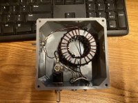
I happen to like the EFHW 80m antenna, with a proper ground. Mine is homemade, but it works on both 80 and 160 (with a switch in the box to switch the transformer primary out and switch in a shunt that converts it to a 1/4 wave on 160 meters (see photo).

The problem on 80 meters is that the feedpoint impedance of a true EFHW is around 5,000 ohm. Not many tuners can handle tuning up a 100:1 VSWR, and even if you have one that can, the voltage in the tuner will likely arc it. So an impedance matching transformer is required with a 1:7 turn ratio between the primary and secondary windings so your antenna tuner can handle tuning it up.

The other caveat is that I consider the 80m EFHW to be a 80/160 antenna only (with a switch in the box to switch out the transformer). It will tune fine on higher bands, but the radiation pattern is less than ideal.

One of the advantages of a true EFHW is that it is a DC grounded antenna. So it tends to have less static hash/background noise than a dipole on receive. The reason is that the radiating element is DC grounded thru the transformer secondary. On 160 meters the primary winding becomes inactive, the high inductive impedance of the transformer secondary pushes the current to the radiator on TX, but on receive it's still DC grounded. As primarily a 80 and 160 operator, it is my favorite antenna. I have my tower loaded up on 160 as a 1/4 wave vertical, but the EFHW in 160 mode is a much better receiving antenna than the tower is, and no real differences on TX that I've ever been able to tell. My EFHW is a sloper - it goes from the outside of my shack wall at ~70 deg angle to the top of my 120ft tower.

So anyway, I don't know that I'd even recommend buying that antenna, especially if you're looking to get on 80 meters with it. I suspect that no matter what orientation you install it, its performance on 80m is likely not that good.
 

Attachments

  • iPhoto-Export - 1.jpeg
    iPhoto-Export - 1.jpeg
    196.5 KB · Views: 9

AC9KH

Member
Joined
Nov 5, 2014
Messages
120
Location
Northern Wisconsin
I would also use a good ferrite based RF choke or 1:1 balun somewhere in the feedline before the grounding point.

Why would you want to use a balun on a random length wire? A balun goes from BALanced load (dipole) to UNbalanced feeder (coax). An EFHW or random length wire is an unbalanced load working against earth ground, fed by an unbalanced feeder. That's why it already has an unun (UNbalanced to UNbalanced), which is another name for the impedance matching transformer.

With the particular antenna in question, which is using the coax shield for a counterpoise, an RF choke would be a good idea before the coax comes thru the shack wall. But you don't need a choke with a ferrite core. An air-core choke consisting of several turns of coax on a former (like a piece of PVC pipe) is all it takes.
 

prcguy

Member
Premium Subscriber
Joined
Jun 30, 2006
Messages
16,326
Location
So Cal - Richardson, TX - Tewksbury, MA
Why would you want to use a balun on a random length wire? A balun goes from BALanced load (dipole) to UNbalanced feeder (coax). An EFHW or random length wire is an unbalanced load working against earth ground, fed by an unbalanced feeder. That's why it already has an unun (UNbalanced to UNbalanced), which is another name for the impedance matching transformer.

With the particular antenna in question, which is using the coax shield for a counterpoise, an RF choke would be a good idea before the coax comes thru the shack wall. But you don't need a choke with a ferrite core. An air-core choke consisting of several turns of coax on a former (like a piece of PVC pipe) is all it takes.
You are right, you don't need a choke with a ferrite core. Unless you actually want it to work.

A ferrite 1:1 choke is a broad band device that reduces common mode currents on the coax shield and it will ABSORB RF and turn it into heat over a very wide frequency range. The more basic types of ferrite chokes can be a string of high permeability beads over the coax shield and with the right mix and minimum amount of beads you can achieve up to about 20dB (100:1 reduction) of common mode reduction which also equates to 20dB of isolation on either side of the choke.

Different designs of ferrite based chokes can achieve up to 30dB (1,000:1 reduction) of isolation using a single ferrite toroid and over 40dB (10,000:1) using multiple wound cores and different ferrite mixes to target different frequency ranges. With 30dB+ you have effectively isolated the antenna system from the radio forcing unbalanced coax to be balanced on the antenna side, stripping off nearly all common mode RF currents that can create problems on transmit in the shack and finally reducing RFI induced onto the coax at the shack end from reaching the antenna making for a lower noise floor.

Now to the ugly balun, which is just some coax wound up into a coil somewhere in the feedline. At one specific frequency where it creates a high impedance to RF it will reduce the flow of RF currents on the coax shield. It does this by REFLECTING RF currents back to the source where it can reflect back up the coax to the antenna in an endless cycle. The frequency where the choke is effective has to be calculated and tested as there are many things that can affect its resonant frequency just like placing a tuned antenna in various places since the environment will skew the resonant frequency of a simple air would coil. Did I mention an air wound coil of coax is only effective at one frequency and it degrades rapidly away from that frequency?

Most people who make an ugly balun don't calculate anything or test how effective it is, they just wind up some coax and assume its doing something, which its not in most cases. And even if they happened across the magic number of windings and size its still only effective at one basic frequency and that's pretty useless over the entire HF range where most ugly baluns are put into service. If done properly for a single narrow frequency range like CB, an ugly balun can reduce RF currents and sort of isolate the antenna system from the radio end, but I've never met anyone who has properly designed an ugly balun for CB.

That's why I recommend a good ferrite based 1:1 choke balun, it is a balun by virtue of high isolation and as an example can transform unbalanced coax to a balanced antenna like a 1/2 wave dipole if it has sufficient isolation and its placed right at the antenna feedpoint. Or in the case of an EFHW (which doesn't need a counterpoise within its resonant ranges) it will reduce the resulting common mode currents on the feedline when operated outside its native resonant ranges and also potentially reduce the receive noise floor if any RFI has been induced onto the feedline at the radio end.

An EFHW using a 64:1 or 49:1 transformer does not need a ground connection or counterpoise to operate, its self contained and stray capacitance within the transformer is enough to simulate a minimal counterpoise. Within its resonant ranges you can place a 40dB isolation choke right at the transformer, test then take it away and there will be no difference in performance or usually VSWR.

So after reading this is anyone in a hurry to wind up an ugly balun out of coax? Anyone reaching for a catalog to price a new ferrite choke balun? Ferrite chokes are not all created the same and some models from MyAntennas like the CMC-130-3K or the Palomar Maxi-Choker or the RF Inquiry CF250E or CF5KV are outstanding broad band high isolation chokes using multiple individual chokes inside a single housing. But they cost a lot of $$. They will fix problems that a simple string of beads over coax cannot or an ugly balun never will.
 
Last edited:

AC9KH

Member
Joined
Nov 5, 2014
Messages
120
Location
Northern Wisconsin
So after reading this is anyone in a hurry to wind up an ugly balun out of coax?

I've used them (air core chokes) regularly over the years, wound with 75 ohm RG-6, and they "just work". The Q of the choke at resonance is not critical. It is a broadband RF choke that works via its inductive impedance, which is high over a wide range of frequencies.

In addition, there is no such thing as an "all band" antenna. Just because you can get a match, or get it to tune, does not mean it is effective. The 80m EFHW in question works on 80 and 160 (as a 1/4 wave on 160 with the transformer out of the primary circuit). But on 40m, for instance, it is a full-wave antenna. It will still work reasonably well on 40 as a vertical, but due to multiple current nodes on the radiator you're already compromising your radiation takeoff angle. It only gets worse as you go higher in frequency on that antenna. That's why I consider it to be a 80/160 antenna only. Start switching to progressively shorter antennas at 60m and above.

The impedance transformer used on the antenna posted by the OP, I would guess, is a 9:1 type for random length wire. So it would have a 1:3 turn ratio between the primary and secondary winding. The homemade transformer I use on my EFHW is 3 turn primary, 21 turn secondary, wound on dual FT240-43 cores. While these antennas will work without an RF ground, that is not optimal and it becomes a compromise antenna. The end of the primary winding, and start of the secondary winding, in the impedance matching transformer on mine is connected to the 130ft ground plane radials for my tower. That makes the difference between an EFHW that works, and one that only kinda works.

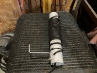
Pictured is an air-core choke that I have used on my 120ft tower, with the tower loaded up on 80 meters as an (electrical) half-wave without the use of an impedance matching transformer. But I prefer the EFHW wire with the transformer on it and no choke. Using the transformer with a good ground plane, there's nothing to choke. You never throw a choke inline just because you THINK it needs it. That's real-world experience, and not theory.
 

Attachments

  • iPhoto-Export - 1 (1).jpeg
    iPhoto-Export - 1 (1).jpeg
    193.4 KB · Views: 7

prcguy

Member
Premium Subscriber
Joined
Jun 30, 2006
Messages
16,326
Location
So Cal - Richardson, TX - Tewksbury, MA
I've used them (air core chokes) regularly over the years, wound with 75 ohm RG-6, and they "just work". The Q of the choke at resonance is not critical. It is a broadband RF choke that works via its inductive impedance, which is high over a wide range of frequencies.

In addition, there is no such thing as an "all band" antenna. Just because you can get a match, or get it to tune, does not mean it is effective. The 80m EFHW in question works on 80 and 160 (as a 1/4 wave on 160 with the transformer out of the primary circuit). But on 40m, for instance, it is a full-wave antenna. It will still work reasonably well on 40 as a vertical, but due to multiple current nodes on the radiator you're already compromising your radiation takeoff angle. It only gets worse as you go higher in frequency on that antenna. That's why I consider it to be a 80/160 antenna only. Start switching to progressively shorter antennas at 60m and above.

The impedance transformer used on the antenna posted by the OP, I would guess, is a 9:1 type for random length wire. So it would have a 1:3 turn ratio between the primary and secondary winding. The homemade transformer I use on my EFHW is 3 turn primary, 21 turn secondary, wound on dual FT240-43 cores. While these antennas will work without an RF ground, that is not optimal and it becomes a compromise antenna. The end of the primary winding, and start of the secondary winding, in the impedance matching transformer on mine is connected to the 130ft ground plane radials for my tower. That makes the difference between an EFHW that works, and one that only kinda works.

Pictured is an air-core choke that I have used on my 120ft tower, with the tower loaded up on 80 meters as an (electrical) half-wave without the use of an impedance matching transformer. But I prefer the EFHW wire with the transformer on it and no choke. Using the transformer with a good ground plane, there's nothing to choke. You never throw a choke inline just because you THINK it needs it. That's real-world experience, and not theory.
I’ve visited countless amateurs with RFI problems where they had an ugly balun choke and I swapped it out with one of my MyAntennas or other high isolation chokes and it cured their problem. If you have success with an ugly balun then you’re lucky and in the minority as they are all different with different levels of isolation and usually not that good.

You definitely don’t want to use a resonant EFHW vertical except on its fundamental 1/2 wavelength due to all the lobes and nulls on the higher bands. I‘ve never heard of anyone doing that. When installed horizontal, especially around 32ft high they make a wonderful multiband and nearly all band 80-10M antenna. I use mine on all bands 80-10m without a tuner except for 60m. An 80M EFHW is basically no different than the old favorite 133ft dipole fed in the center with 450-600 ohm balanced line and tuned with a balanced tuner. The radiation characteristics with gain lobes and nulls are nearly the same.

At around 32ft off the ground a 133ft EFHW makes an excellent NVIS antenna on 80 and 40m which can also work ok for DX. On 20m and up it’s a good low angle DX antenna.
 

AC9KH

Member
Joined
Nov 5, 2014
Messages
120
Location
Northern Wisconsin
You definitely don’t want to use a resonant EFHW vertical except on its fundamental 1/2 wavelength due to all the lobes and nulls on the higher bands. I‘ve never heard of anyone doing that.

Very few people have vertical EFHW antennas on 80m. With mine I get roughly 20dB of attenuation on 80m between my vertical and stations using dipoles out to ~300 miles. That's a loss of about 3 S-units in signal, which I make up for with the amplifier for local ragchewing on 80. Out beyond ~300-500 miles the vertical is better because it has a lower radiation takeoff angle and it reduces the number of hops to get to the destination. Also, vertical-to-vertical, groundwave is no problem on 80m @ 100 miles and 100W PEP.

On 160, most serious operators are using verticals, and that's where the vertical EFHW switched to 160 mode really shines. 160 is a noisy band and the EFHW in 160 mode can pull signals out of the noise floor that dipoles can't. My tower is an isolated radiator and I've contemplated trying a DC-grounded setup with the tower on 160 to see if it can match the EFHW for SNR. But have never gotten around to it. Loading up a tower is a different animal due to the electrical diameter of it vs a wire, and it's not quite as easy, especially due to interaction with the guy wires. So the tower is just inherently more noisy on receive than the EFHW wire is, although they work equally well on Tx.

BUT, for people wanting to get on the Top Band, the EFHW 80m wire, with the transformer primary switched out, makes a reasonably compact antenna that works. And I think it would work as an inverted V configuration on 160 if you can get the peak of the V to about 50-60 ft and the ends of the wire about 10 ft off the ground. I've never actually tried that, but I see no reason why it wouldn't work, and would be fairly easy to install vs a 260ft dipole that would need to be 130 ft off the ground, and then deal with getting a feedline to the center of it.

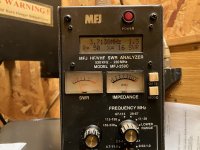
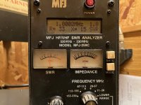
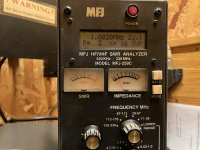
Shown is the results of my EFHW vertical in the center of the 80m band, and on the bottom of the 160 band (with the transformer primary switched out). I typically use the amplifier on 160 (tube type) and don't bother tuning it up <3.0:1. The third photo is what it is in 80m mode on 160. Trying to tune the EFHW on 160 @ 22:1 would turn your tuner into a smoldering pile of ash, but it's a perfectly usable 1/4 wave if you do the modification to switch the transformer primary out and use the secondary as a high-impedance RF choke.

iPhoto-Export - 1.jpeg

iPhoto-Export - 2.jpeg

iPhoto-Export - 1 (1).jpeg
 

RadioDXfun

Omni low angle radiator
Joined
Dec 14, 2021
Messages
52
Location
United Kingdom
I just add my confirmation of what has been said by people with wider antenna knowledge. I use single band EFHW verticals that I have made DIY. This was to avoid the small ferrite cores which occupy many if you buy an 'Ebay' antenna from another ham (I overheated some and SWR went skywards fast, not burnt out but long overs at 100W PEP SSB still caused issue on small cores). At least for verticals, it is almost impossible to make a single wire piece antenna perform better for DX than 1/2 wave cut for one single band elevated as high as possible.

It is my personal finding they equal even 5/8th waves assuming same tip height which I have made an used as well and yet require no large radial field. And often you can get the 1/2 wave up higher with less practical problems. Often I can feed my 10m band 1/2 wave vertical EFHW at 13-15m portable which gives considerable gain at 5 degrees over a ground mounted 1/4 wave (I make it 7.5dBi according to models and that is not to be sniffed at for TX and RX. Much DX on 10m comes in and out at 5 degrees +/- 3 degrees)

I only work portable radio and so I appreciate most hams want to be on as many bands as possible. I do not see it like that myself. I go out and generally stay on 1 band and focus on that band and work it the best I can. I have a 1/2 wave for 20m through 10m

Just the once I used a EFHW vertical on 40m (I just extended my 20m band one) using 20m fibre glass pole when the wind was just 3-4mph.

I am not much of an experimenter. I find what seems to work best on most occasions and use that.

Verticals are easier to set up than horizontals for portable and the 1/2 waves equal the 5/8 wave and beat the 1/4 waves significantly as they are elevated and have no radials to concern with. Yesterday 6,800miles to Argentina was achieved on 10m, ok not a very difficult path from the UK to be honest but in a low noise countryside spot they do me as good as anything will.

Sometimes a vertical can even beat a low mounted beam for super low angle gain through elevation (if such a path is open) and no need to spin it so you can intercept and TX very fast. I could never get a 3 ( or even 2) element beam for 10m fed at 15m portable.
 
Last edited:
Top