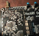
Here is my evaluation of the HackRF portapack H2 I just purchased this week(9/23/22). Looks like its been out for a year or two. Very impressed with it, much nicer than the usual laptop PC + USb method of using sdr's.
I have had a hackrf one for a couple of years. While looking at something else I came across the H2 portapack board on Ebay and some completed integrated units as well. After a little read about it this seemed like a very good idea to get one or two of these. Lots of interesting features and ability to perform most of the functions that can be done on a PC with the HackRF. Checklist: its a HackRF one, yes.
Plug in socket pin pattern matches. I ordered complete H2Portapack and
ordered a second add on to put with my existing hackRF. From what I've read you need to reflash the HackRF thats where the searial flash is located, to install the mayhem firmware.
This consists of the board and a battery and a speaker connector with wires. There was no speaker with this kit. There was no SD card. It will run without it but the ADSB map, aircraft database is there. I found a sample SD card contents on github.
Custom firmware for the HackRF SDR + PortaPack H1 addon - furrtek/portapack-havoc

github.com
Download as zip then extract it on a PC, and you will need to modify freq ranges for the bands that are of interest, keep a folder handy to work on it.
I found world_map.bin but it doesnt work right so I'll have to run the python script explaned in the docs to create it. It converts workd_map.jpg to a custom format.
Here are some basics I have not found documented:
Turning it off: double tap the rotary knob it goes left right and in, single tap to turn back on.
Took me a couple of days to find that, I was getting ready to put a switch on the battery.(H2) I never had an H1, I haven't found any open source on that board either.
Top row highlight using the 5 buttons and click center to turn on or off: Speaker, Stealth (blank screen while tx), screenshot, display sleep, bias tee, clock out, sd status.
RF in/out comes in or out of the top connector.
Amp 1: High band above UHF.
Amp 0: low band down to about 1 mhz.
DC bias for antenna preamps: 3.2 volts, active when receive is running.
Clock out: 3.3volts Peak to Peak defaults to 10mhz. There is 10mhz present on the clock in terminal at a lower amplitude.
When pulling the USB go to the top menu so there are no SD writes going on, this seems to reset everything.
Looking glass: wide band spectrum sweeps.
You can set Low Noise Amp Gain, Variable Gain Amp Gain, preset which is selected with buttons then rotate the knob to select an item (freq range) in the lookinglass.txt file , set the marker to identify a signal line, and resolution, lower for fast changing signals like hoppers, slow for weaker signals that don't change.
Move marker near a signal of interest, press center button, this puts you into drill down receiver mode in that sub band.
Edit the preset file 'lookingglass.txt' on the sd card to edit ranges for your area. Edit on the pc then transfer to the SD card, at your convenience.
Microphone: There is a 3 pin 3.5mm connector on the bottom of the H2 board,
You can use a 3 pin headset 3.5mm to connect left, right and mic to the unit.
I used a pc type stereo earphone with microphone. I heard a click when plugging it in, indicating there is a dc bias for electret mics, on the third pin of the jack.
I set up the rx and tx frequencies in nbfm and tuned another transceiver to the channel, and it works! Both receiving and transmitting, you have to set up the receive and transmit frequencies separately, There is plenty of audio gain. If the source were to be a line input then it would feed into the third pin of this jack with a splitter cable for compact PC's that have only a headset jack.
When receiving I hear a zero crossing heterodyne (from the local oscillator?) meaning there is no offset between the local oscillator and the 'dc frequency' so it has that problem, in this case its a strong signal. When it receives in this mode I hear this as a buzz added to the audio at the sub audio tone rate.
This can transmit AM FM USB LSB and CW, on the tuned frequency, set via the menu on the tx page selects bandwidth and gain. Gain sets up output power 0 to 47. highlight the Tx button and press center to key, set up roger beep and sub audio tone as required.
If you set up a receive mode that is how the transmit mode is set.
That is pretty cool, an all mode transmitter exciter!!!
Range, very solid signal to a scanner at 200 feet, probably can go a lot farther than that with the 20mw or so of power. Next project sweep the frequency.
Battery: appears to charge whenever the USB is connected. Run time about 4 hours, some decrease on high cpu usage apps. The unit will not shut off when USB power is applied.
Hope that helps, I learned a lot just figuring this thing out.
I tried to pick up GOES satellites but found out they don't have analog downlinks anymore and the downlinks are much different, also noted some local ground signals getting through on that band from spurious. A big antenna was used but could not find the downlinks, not sure of the EIRP on this but an LNA or preselector filter will be required.
I tried it on a KU satellite IF and known signals can be seen on it but what you see on the FFT varies alot with many of the settings.
Most notable is averaging settings, in the receive mode, custom settings, there is an averaging number 0 to 63, the lower that is the faster the FFT will run, and small pulses can be found, though the gain has to be increased either in the LNA or VGA.
There is no amplitude calibration, so a signal generator reference would be needed, screenshot, then you have all the gain settings, then tune to the frequency in question and feed the signal generator in, start low and work your way up in amplitude until the level is matched. Sounds like a lot of work.
While tuning around I do see the spurious responses. The front end is wide open so the local oscillator harmonics seem to mix with strong cell band signals and wifi so these appear when tuned to 1/2 1/3 or 1/4 the frequencies such as 2.45ghz and 740, 880, 1950 wherever strong signals are found.
You can tell which ones are spurious because when tuning up the spurios may be going down or moving at a different rate then the real signals. I have a lot of this noise around the house even when I live 3 miles from the nearest cell towers.
Hope that helps -Chris