Hot EFHW Capacitor

NO6GN

Newbie
Joined
May 26, 2021
Messages
4
Reaction score
0
Hi All,

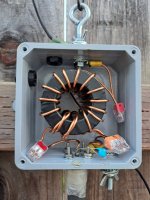
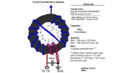
I have an 80-10m EFHW in an inverted V format with a 49:1 unun that I built myself (not from a kit). I designed it to handle high power (1.5-2kW) and was my first ever build and first ever EFHW. It consists of three stacked FT240-61 toroids wrapped with 12G enameled copper wire and a 10kV 100 pF capacitor between the center conductor and ground to help with SWR on 17-10m.

This antenna has performed very well on all bands (phone and digital), so far, and have received good reports on signal strength. However, after a recent rain (maybe it's a coincidence), I have been encountering an issue on 17-10m where the SWR will quickly climb when transmitting barefoot at 75-100W. Thinking that I had water intrusion somewhere, I checked the outside connections and unun. All dry. I did observe that the capacitor was getting very hot, measuring near 150°F at one point. All other components in the unun remained cool. This may be what is causing the SWR to climb. I replaced the capacitor like-for-like and observed the same thing. How can I resolve this, short of immersing the capacitor in a small bath of mineral oil? Or, is this a performance characteristic of an EFHW?

Regards,
-Justin (NO6GN)
 

NO6GN

Newbie
Joined
May 26, 2021
Messages
4
Reaction score
0
I did some further investigating and have determined that a current is being drawn through the capacitor to ground via the ground strap of the lightning arrestor (PolyPhaser IS-50UX-C0). This was a recent addition, and has convinced me that this issue is not due to the recent rain. The arrestor is attached directly to the feed of the unun, and the coax to the arrestor. When I detached the ground strap, the heating and climbing SWR issues went away on the lower bands. I am guessing that, without the nearby ground, the current then has to meet the resistance of the shielding outer braid of the long coax and is dissipated through that.

I have seen many examples of EFHW ununs being grounded, but no discussion about hot capacitors. Have I installed the arrestor in the wrong location, or am I looking poor quality capacitors? I have ordered TDK brand capacitors just in case. Even though I don't live in a high lightning risk area, I would like to have peace of mind.

Attached is a picture of the unun, minus the lightning arrestor.
 

Attachments

  • 20250823_1910241.jpg
    20250823_1910241.jpg
    85.9 KB · Views: 12

NO6GN

Newbie
Joined
May 26, 2021
Messages
4
Reaction score
0
Would adding a resistor between the capacitor and ground to force the current into the coax shield be advisable? I just don't see a resistor being part of any EFHW designs or on any commercial products. I would rather fix whatever is wrong with my build.
 

prcguy

Member
Joined
Jun 30, 2006
Messages
17,868
Reaction score
13,384
Location
So Cal - Richardson, TX - Tewksbury, MA
Something is very wrong and there should be very little current flowing in a 100pf cap across a 50 ohm HF circuit. I've built dozens of EFHW transformers, some with cap voltage values on the edge and never had a problem. First off you don't need a 10kV cap, its across the 50 ohm connector and a simple ohms law calculation will give you expected voltages. For example, 1500w across 50 ohms is 273V and if the feedpoint impedance rises to 100 ohms for some reason there would be 387V. Even if that's an average voltage, peak to peak would be 774V and I might choose a 1.5kV rated cap to be safe.

Second, you can't use three stacked 61 mix cores for an EFHW that works to 10m, its probably fine through 40m but its too much inductance for anything higher. Its common to use three 52 mix cores to cover 80-10m without heating up the cores too much. For a single core #43 mix seems to work fine and a #62 is probably better.

I can't see all the details on your windings but it does seem like the 100pf (blue?) cap is right across the 50 ohm input but the leads are a bit long. There should be a twisted pair ground for the primary going to the ground and I only see one wire. Here is a picture of a MyAntennas 3 stackd core that I placed in another enclosure. Notice the windings are tight together for the first 7 turns and how it crosses over to the final 7 turns with wider spacing but not too wide. Also notice the twisted pair ground gong to the ground connection on the connector. These are probably the best transformers on the market and its best to copy the best.

2kw-transformer-jpg.92711


Otherwise I suspect you have a mistake in winding or in feeding the twisted pair primary and its ground and maybe the cap is seeing more than the 50 ohm input. BTW I don't know what mix ferrite MyAntennas uses. I had a conversation with Danny at MyAntennas and the only thing he would confirm is he doesn't use #43 mix for his EFHW cores. The triple stacked core here has to be much lower permeability than 43 or 62 mix otherwise it would not work as well as it does up through 10m.
 

NO6GN

Newbie
Joined
May 26, 2021
Messages
4
Reaction score
0
Hi preguy,

Thank you for the response! Yes, ferrite mix is the guarded secret sauce for most of the antenna manufacturers. I used the Mix 61 based on the "Up to 2,5KW version – 1" build by this fabricator (49-56-64:1 Ununs) that surprisingly reveals many details about their products. I just didn't match their wrap and capacitor. I'm doing that next. I have read that the tapped single winding is more efficient (All Wound Up About EFHW Transformer Winding).

As for my current build, I followed as closely as I could the attached diagram. Though it's hard to see, the 3-gang connector on the right takes the two twisted ground wires and a third from the coax common and counterpoise which I have attached together. I wanted to make it easy to swap cores for experimentation. The twists are indeed sloppy and I struggled with the 12G wire. I agree the capacitor leads are long and I will shorten them when the new TDK capacitors from Mouser arrive (the current capacitor I got off of Ebay and I suspect it). I'll double check all of the connections when I replace the capacitor, and report in.

Regards,
Justin
 

Attachments

  • 1-49-unun-for-end-fed-half-wave-antennas.jpg
    1-49-unun-for-end-fed-half-wave-antennas.jpg
    40.1 KB · Views: 4

prcguy

Member
Joined
Jun 30, 2006
Messages
17,868
Reaction score
13,384
Location
So Cal - Richardson, TX - Tewksbury, MA
Hi preguy,

Thank you for the response! Yes, ferrite mix is the guarded secret sauce for most of the antenna manufacturers. I used the Mix 61 based on the "Up to 2,5KW version – 1" build by this fabricator (49-56-64:1 Ununs) that surprisingly reveals many details about their products. I just didn't match their wrap and capacitor. I'm doing that next. I have read that the tapped single winding is more efficient (All Wound Up About EFHW Transformer Winding).

As for my current build, I followed as closely as I could the attached diagram. Though it's hard to see, the 3-gang connector on the right takes the two twisted ground wires and a third from the coax common and counterpoise which I have attached together. I wanted to make it easy to swap cores for experimentation. The twists are indeed sloppy and I struggled with the 12G wire. I agree the capacitor leads are long and I will shorten them when the new TDK capacitors from Mouser arrive (the current capacitor I got off of Ebay and I suspect it). I'll double check all of the connections when I replace the capacitor, and report in.

Regards,
Justin
I look at MyAntennas as the gold standard and Danny really knows what he is doing, unlike most mfrs who are not actual antenna engineers with a degree. For example the MyAntennas 2kW rated 1.8 to 30MHz 49:1 is rated .5dB loss worst case over the entire range and its basically the same schematic as the diagram you posted but with different spacing between windings. The diagram is also wrong recommending two stacked 43 cores for 80-10m, that is too much inductance for the upper bands and 62 mix would be better and the ideal mix might be something different that nobody will tell us. I've made a number of dual stacked 43 mix cores and they were great on 80 and 40m but 10m didn't work out very well.

If you look at the MyAntennas MEF 307 transformer that only covers 80-40m its only got .2dB loss and handles up to 4kW. That uses three cores of 3.1" but the core mix is a mystery. Its also a 70:1 ratio for 50/3500 ohm transformation.

On twisting the primary winding, I put two wires in parallel to start, one long enough for the entire run around the transformer and the other long enough for the primary then I clamp the wire in a vice with the two primary sides sticking out its entire length with something soft around the wires in the vice to protect them from the vice jaws. Then stick the two now equal length primary wires in a hand held drill chuck and twist away.

When winding the transformer I lay the junction of the primary/secondary wires up against the outside bottom of the core getting the hot side of the primary pointing outward like its heading towards the connector then I Ty-Wrap it down and start winding the primary by pushing the middle of the wire through the core hole and not the end like you are threading a needle. Pushing the middle of the wire through then pulling the loose end though will hug the core better than threading the end of the wire through first. When the primary ground side has its two windings Ty-Rap that down and start pulling the secondary wire through using the middle of the wire technique until it looks like the picture of the MyAntenns core I posted. I would study that picture closely to make sure the windings head the same direction and the placement of the primary wires as in the single hot and dual ground are oriented the same and you wind everything in the same direction as the picture. The lessen here is don't mess with something that works, just copy it.
 
Last edited:
Top