How Is Powering An LNA Best Accomplished?

Status
Not open for further replies.

Ubbe

Member
Joined
Sep 8, 2006
Messages
9,788
Location
Stockholm, Sweden
If you consider that HPN-30118 then you can take off its lid and you'll see one of the biggest coils at the female BNC connector that goes to ground. Try separating the turns a little. You'll see that being done to other coils as well to tune them. You'll see the two other biggest coils at the male BNC connector but don't touch those. When you seperate the turns it will loose some inductance and do not couple the low frequency part of the filter to ground as much, and the 86Mhz frequency will not be attenuated as much but will also pass a bit more of the 88Mhz range.

I don't have that strong FM broadcast signals at my place, all signals are low, so I use filters between amplifier and receiver and when measure the sensitivty by inserting a signal in parallell to the antenna coax I get no change in sensitivity or intermod with any scanner regardless of where I install the filter. Then any filters insertion loss are of no concern if the amplifier are first in the signal chain from the antenna . So try that setup first to see if the amplifier can handle it. Using a PGA103+ it needs to be a pretty strong signal for that to happen, perhaps using a discone, that works best on the FM band, and at the same time being close to a FM broadcast transmitter can make it happen.

/Ubbe
 

Merovingian

Member
Joined
Sep 17, 2006
Messages
206
If you consider that HPN-30118 then you can take off its lid and you'll see one of the biggest coils at the female BNC connector that goes to ground. Try separating the turns a little. You'll see that being done to other coils as well to tune them. You'll see the two other biggest coils at the male BNC connector but don't touch those. When you seperate the turns it will loose some inductance and do not couple the low frequency part of the filter to ground as much, and the 86Mhz frequency will not be attenuated as much but will also pass a bit more of the 88Mhz range.

I don't have that strong FM broadcast signals at my place, all signals are low, so I use filters between amplifier and receiver and when measure the sensitivty by inserting a signal in parallell to the antenna coax I get no change in sensitivity or intermod with any scanner regardless of where I install the filter. Then any filters insertion loss are of no concern if the amplifier are first in the signal chain from the antenna . So try that setup first to see if the amplifier can handle it. Using a PGA103+ it needs to be a pretty strong signal for that to happen, perhaps using a discone, that works best on the FM band, and at the same time being close to a FM broadcast transmitter can make it happen.

/Ubbe

Thanks, thats good information. I was planing to insert the filters between the antenna and amplifier, rather than the amplifier and receiver. I was thinking it would be better to suppress the unwanted frequencies before I amplify it.
 

Ubbe

Member
Joined
Sep 8, 2006
Messages
9,788
Location
Stockholm, Sweden
I was thinking it would be better to suppress the unwanted frequencies before I amplify it.
That depends of the amplifiers quality as it doesn't matter to the signal levels. The resulting difference in level of FM broadcast and other frequencies outside of the filters range will be exactly the same. But amplifying first will make the filters loss figure redundant and you will gain that loss in a better system noise figure. All bandstop filters have loss but the expensive ones have less loss, but the difference in cost are much more than what a good amplifier costs.

You will need to have RF levels of the region of -10dBm from a single transmitter to have any impact on a PGA103+ amplifier. Very few people have that. If you have several strong transmitters their combined signal strenght can be an issue, but if they all are below -20dBm then it shouldn't matter. Anyhow so will any scanner have gotten into trouble long before the amplifier does.

/Ubbe
 

Merovingian

Member
Joined
Sep 17, 2006
Messages
206
That depends of the amplifiers quality as it doesn't matter to the signal levels. The resulting difference in level of FM broadcast and other frequencies outside of the filters range will be exactly the same. But amplifying first will make the filters loss figure redundant and you will gain that loss in a better system noise figure. All bandstop filters have loss but the expensive ones have less loss, but the difference in cost are much more than what a good amplifier costs.

You will need to have RF levels of the region of -10dBm from a single transmitter to have any impact on a PGA103+ amplifier. Very few people have that. If you have several strong transmitters their combined signal strenght can be an issue, but if they all are below -20dBm then it shouldn't matter. Anyhow so will any scanner have gotten into trouble long before the amplifier does.

/Ubbe

Ahhh, I see. Thanks again for the good information! When I am able to get this built I will put the pre-amp first.
 

prcguy

Member
Premium Subscriber
Joined
Jun 30, 2006
Messages
16,641
Location
So Cal - Richardson, TX - Tewksbury, MA
Always put the filter before the preamp, never put the preamp before the filter. The only exception to this is if you are not going to connect an atnena to the preamp and filter like on a test bench for sweeping or testing. Or you need to generate some IMD to play with.

The statements about not generating IMD unless you get to -20dBm are not true and a PGA103+ amplifier or most low level preamps with a bunch of signals off an antenna at a much lower level will generate lots of IMD that you will hear on your receiver. It might be distinct transmissions you will hear that don't belong on the frequency you hear them on or typically it will be a higher noise floor from hundreds or more frequencies mixing into a sea of low level IMD that looks like noise.


Ahhh, I see. Thanks again for the good information! When I am able to get this built I will put the pre-amp first.
 

Merovingian

Member
Joined
Sep 17, 2006
Messages
206
I see. Thanks for the correction. I thought it was better to filter first but I'm new to this type of thing so what do I know. . . I'm glad to have multiple sources of advice. Thanks!

Always put the filter before the preamp, never put the preamp before the filter. The only exception to this is if you are not going to connect an atnena to the preamp and filter like on a test bench for sweeping or testing. Or you need to generate some IMD to play with.

The statements about not generating IMD unless you get to -20dBm are not true and a PGA103+ amplifier or most low level preamps with a bunch of signals off an antenna at a much lower level will generate lots of IMD that you will hear on your receiver. It might be distinct transmissions you will hear that don't belong on the frequency you hear them on or typically it will be a higher noise floor from hundreds or more frequencies mixing into a sea of low level IMD that looks like noise.
 

prcguy

Member
Premium Subscriber
Joined
Jun 30, 2006
Messages
16,641
Location
So Cal - Richardson, TX - Tewksbury, MA
One of the best known preamps for repeater front end use was Angle Linear, and I've had the owner of Angle Linear (Chip) sit me down and explain the do's and don'ts of using his or any preamp and how easy it is to generate IMD in even the highest level version that Angle Linear made and it was very enlightening. Chip calculated out a couple of surprisingly low level signals that would start making IMD in the low -90dBm range which will be heard just fine in your receiver as interference. So even with these industry standard, high level preamps that would put out a hefty one watt of signal, they needed to have very narrow and tight band pass filters in front of them to perform to spec so mountain top repeaters would actually benefit from the addition of a preamp and not get trashed from IMD.

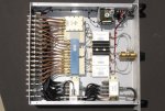
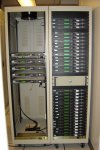
For another example, below are pictures of a test station I built that generated up to 32 carriers for testing satellite receivers. I hand built most everything and still ended up spending $250k in components. I took a chance with the amplifiers in the picture looking inside a box where you can see some MiniCircuits ZRL-2150 amplifiers. These are rated around 22dBm output for 1dB compression and 33dBm IP3. Each ZRL-2150 amplifier had to amplify only 8 carriers to a level of -19dBm each for an aggregate level of around -10dBm.

During testing I found when the 8 carriers reached a level of around -29dBm each out of the amplifier, or 10dB below the needed spec, the noise floor out of the test station had already risen about 5dB due to a lot of IMD that was being generated in the amplifiers from the 8 carriers at the amplifier input. You could see it clearly as the output level is raised slowly and then like magic, or horror, the noise floor starts raising at a rate twice what the wanted signals are going up as you increase levels past the point where IMD is generated. Since the amplifiers have about 25dB of gain, the 8 carriers feeding the amplifier were only around -54dBm each when IMD had already set in, which is roughly a signal on a receiver of S-9 +20dB, strong but not that strong and you will probably have lots of signals at least that strong off a Discone at any given time.

The amplifier specs in my test station are not that different than what you might use for a higher end preamp at home but your antenna will be picking up hundreds or more signals and some will be higher than -54dBm. Use a wide band preamp with no preselector filter or put the preamp before the filter and you will have a mess.

In the end my test station was accepted and did a great job for my company and they had me build a second "box" with upgraded higher level and much more expensive amplifiers and other components and that fixed most of the IMD problem. It was also a great learning experience in amplifier selection and keeping IMD in check. So here are some real life experience with amplifiers and IMD and some signal levels that can ruin your day with a preamp.

3.JPG7.JPG


I see. Thanks for the correction. I thought it was better to filter first but I'm new to this type of thing so what do I know. . . I'm glad to have multiple sources of advice. Thanks!
 

Merovingian

Member
Joined
Sep 17, 2006
Messages
206
Very enlightening explanation! That box in the picture looks very impressive, so many ports, it must have taken many, many hours to build that.

Having the pre-amp and filters raise the noise floor is one thing I am worried about, I want all of the gain I can get with out adding problems/noise to the signal. For this project I will only be focusing on 34 MHz of spectrum between 54MHz and 88MHz but primarily around 54MHz-60MHz. The signals I want to receive will be somewhat weak so I'm glad for any help and advise I can get to I can try to do this correctly. Having two similar filters won't cause problems will it? The Mini-Circuits to filter most of the frequencies I don't want and the HPN-30118 Combined Notch Filter | Scanner Master to help better suppress the FM frequencies the other filter doesn't?

I put in an order for the antenna yesterday, I haven't heard from the company yet, hopefully they will get back to me soon. After I have that, I can move forward with the filters.


One of the best known preamps for repeater front end use was Angle Linear, and I've had the owner of Angle Linear (Chip) sit me down and explain the do's and don'ts of using his or any preamp and how easy it is to generate IMD in even the highest level version that Angle Linear made and it was very enlightening. Chip calculated out a couple of surprisingly low level signals that would start making IMD in the low -90dBm range which will be heard just fine in your receiver as interference. So even with these industry standard, high level preamps that would put out a hefty one watt of signal, they needed to have very narrow and tight band pass filters in front of them to perform to spec so mountain top repeaters would actually benefit from the addition of a preamp and not get trashed from IMD.

For another example, below are pictures of a test station I built that generated up to 32 carriers for testing satellite receivers. I hand built most everything and still ended up spending $250k in components. I took a chance with the amplifiers in the picture looking inside a box where you can see some MiniCircuits ZRL-2150 amplifiers. These are rated around 22dBm output for 1dB compression and 33dBm IP3. Each ZRL-2150 amplifier had to amplify only 8 carriers to a level of -19dBm each for an aggregate level of around -10dBm.

During testing I found when the 8 carriers reached a level of around -29dBm each out of the amplifier, or 10dB below the needed spec, the noise floor out of the test station had already risen about 5dB due to a lot of IMD that was being generated in the amplifiers from the 8 carriers at the amplifier input. You could see it clearly as the output level is raised slowly and then like magic, or horror, the noise floor starts raising at a rate twice what the wanted signals are going up as you increase levels past the point where IMD is generated. Since the amplifiers have about 25dB of gain, the 8 carriers feeding the amplifier were only around -54dBm each when IMD had already set in, which is roughly a signal on a receiver of S-9 +20dB, strong but not that strong and you will probably have lots of signals at least that strong off a Discone at any given time.

The amplifier specs in my test station are not that different than what you might use for a higher end preamp at home but your antenna will be picking up hundreds or more signals and some will be higher than -54dBm. Use a wide band preamp with no preselector filter or put the preamp before the filter and you will have a mess.

In the end my test station was accepted and did a great job for my company and they had me build a second "box" with upgraded higher level and much more expensive amplifiers and other components and that fixed most of the IMD problem. It was also a great learning experience in amplifier selection and keeping IMD in check. So here are some real life experience with amplifiers and IMD and some signal levels that can ruin your day with a preamp.

View attachment 89722View attachment 89723
 

prcguy

Member
Premium Subscriber
Joined
Jun 30, 2006
Messages
16,641
Location
So Cal - Richardson, TX - Tewksbury, MA
Are you going to be receiving TV signals? If so with the antenna horizontal? Here is an interesting antenna and I had one for awhile but gave it to a friend because I didn't need a directional antenna in the 30 to 76Mhz range. I believe its got around 4.5dB gain and its a wire log periodic that folds up. It can be mounted horizontal or vertical and its very expensive new but this one is very cheap.

Very enlightening explanation! That box in the picture looks very impressive, so many ports, it must have taken many, many hours to build that.

Having the pre-amp and filters raise the noise floor is one thing I am worried about, I want all of the gain I can get with out adding problems/noise to the signal. For this project I will only be focusing on 34 MHz of spectrum between 54MHz and 88MHz but primarily around 54MHz-60MHz. The signals I want to receive will be somewhat weak so I'm glad for any help and advise I can get to I can try to do this correctly. Having two similar filters won't cause problems will it? The Mini-Circuits to filter most of the frequencies I don't want and the HPN-30118 Combined Notch Filter | Scanner Master to help better suppress the FM frequencies the other filter doesn't?

I put in an order for the antenna yesterday, I haven't heard from the company yet, hopefully they will get back to me soon. After I have that, I can move forward with the filters.
 

Merovingian

Member
Joined
Sep 17, 2006
Messages
206
I have never seen an antenna like that. 8' X 8' is pretty big. I would think it receives signals edge on? Or face on? The price isn't too bad though.

Yes, I'm building a forward scatter meteor detection station. I'm attempting to receive DTV pilot carrier frequencies from TV channel 2 and channels 2-6 if I can. I'm planning to point the antenna straight up rather than toward the horizon, I'm not really interested in seeing how far away of a TV signal I can receive but how many meteors I can detect overhead which is why I'm wanting an antenna that has very little directivity, something that can "see" the whole sky.

I have done some research and found that there are about 15 stations operating between channels 2-6 within 350 miles or so of my location. One of those is on channel 2 within 100 miles and 5 stations less than 200 miles away on channels 2, 4, 5 and 6. The transmitting power for those stations ranges between 10 kW and 34 kW, the one that is less than 100 miles away transmits at 33 kW.

I chose DTV because there is not much choice in the US when it comes to continuous, high power transmitters to reflect off of the ionised trail from a meteor. The US use to operate a radar fence in Texas but they shut that down so that leaves no other options but DTV. There are no stations in my area transmitting between channels 2-6 so those frequencies should be quite as far as TV signals go, so anything received should be reflected from a meteor trail.


Are you going to be receiving TV signals? If so with the antenna horizontal? Here is an interesting antenna and I had one for awhile but gave it to a friend because I didn't need a directional antenna in the 30 to 76Mhz range. I believe its got around 4.5dB gain and its a wire log periodic that folds up. It can be mounted horizontal or vertical and its very expensive new but this one is very cheap.
 

Ubbe

Member
Joined
Sep 8, 2006
Messages
9,788
Location
Stockholm, Sweden
The antenna you have ordered can be tuned between 50-85Mhz but it is only 4MHz wide from the tuned frequency. It has one reflector element and if all backloob signal in a half circle behind the antenna can be reflected without loss you get a 3dB gain. But it will only reflect a small part.

As you have the elements horisontal you can turn the antenna around its axel to reduce the strongest interfering signals from the sides. But it should be pretty quiet in that band. If you put two filters before the amp you will reduce the signal more than 3dB, so try first with the amp directly to the antenna. You shouldn't have much RF energy from that antenna to cause any problems. It's like anything else related to radio and antennas, just test and see if it works. It's impossible to know how it will work until tests have been done at a specific location.

/Ubbe
 

prcguy

Member
Premium Subscriber
Joined
Jun 30, 2006
Messages
16,641
Location
So Cal - Richardson, TX - Tewksbury, MA
It is an odd antenna but its real and many of them were deployed in South East Asia in the late 1960s and 70s. Its directional off one edge and if you look closely at the picture of it assembled on the ground there will be an arrow pointing in the direction of max radiation. To point it straight up would be easy.

If you saw one in person you would know $125 is cheap for what it is. The only thing that might be better is a military log periodic made by Hy-Gain that covered the same frequency range but was a more traditional log with snap together aluminum elements.

I think the best thing for what you are doing is a lot of gain in the antenna and maybe a preamp to make up for feedline loss and to set the noise figure as low as possible. The signals you are looking for will be very weak.

I have never seen an antenna like that. 8' X 8' is pretty big. I would think it receives signals edge on? Or face on? The price isn't too bad though.

Yes, I'm building a forward scatter meteor detection station. I'm attempting to receive DTV pilot carrier frequencies from TV channel 2 and channels 2-6 if I can. I'm planning to point the antenna straight up rather than toward the horizon, I'm not really interested in seeing how far away of a TV signal I can receive but how many meteors I can detect overhead which is why I'm wanting an antenna that has very little directivity, something that can "see" the whole sky.

I have done some research and found that there are about 15 stations operating between channels 2-6 within 350 miles or so of my location. One of those is on channel 2 within 100 miles and 5 stations less than 200 miles away on channels 2, 4, 5 and 6. The transmitting power for those stations ranges between 10 kW and 34 kW, the one that is less than 100 miles away transmits at 33 kW.

I chose DTV because there is not much choice in the US when it comes to continuous, high power transmitters to reflect off of the ionised trail from a meteor. The US use to operate a radar fence in Texas but they shut that down so that leaves no other options but DTV. There are no stations in my area transmitting between channels 2-6 so those frequencies should be quite as far as TV signals go, so anything received should be reflected from a meteor trail.
 

Merovingian

Member
Joined
Sep 17, 2006
Messages
206
The antenna you have ordered can be tuned between 50-85Mhz but it is only 4MHz wide from the tuned frequency. It has one reflector element and if all backloob signal in a half circle behind the antenna can be reflected without loss you get a 3dB gain. But it will only reflect a small part.

Yeah, I'm going to see if they can tune it to around 54.310 MHz since that is my primary interest. If that comes about and I am able to get this system put together I'll have to see how badly out of tune it is for the other 4 frequencies I also would like to be able to receive.

As you have the elements horisontal you can turn the antenna around its axel to reduce the strongest interfering signals from the sides. But it should be pretty quiet in that band. If you put two filters before the amp you will reduce the signal more than 3dB, so try first with the amp directly to the antenna. You shouldn't have much RF energy from that antenna to cause any problems. It's like anything else related to radio and antennas, just test and see if it works. It's impossible to know how it will work until tests have been done at a specific location.

/Ubbe

Yes, I will give it a try, hopefully by then I'll have the NanoVNA I am wanting to get so I can have some sort of test equipment to use.
 

Merovingian

Member
Joined
Sep 17, 2006
Messages
206
It is an odd antenna but its real and many of them were deployed in South East Asia in the late 1960s and 70s. Its directional off one edge and if you look closely at the picture of it assembled on the ground there will be an arrow pointing in the direction of max radiation. To point it straight up would be easy.

I looked again at the picture but I didn't notice the arrow, but I take your word for it.

If you saw one in person you would know $125 is cheap for what it is. The only thing that might be better is a military log periodic made by Hy-Gain that covered the same frequency range but was a more traditional log with snap together aluminum elements.

That antenna does look heavy duty, it requires a 3" diameter pipe to mount it. I will have to think about it some more. If I don't hear from those guys in Italy about my order I will probably plan on buying this one, it does have the frequency range I'm looking for. I'm not sure about the directivity of it.

I think the best thing for what you are doing is a lot of gain in the antenna and maybe a preamp to make up for feedline loss and to set the noise figure as low as possible. The signals you are looking for will be very weak.

An antenna with a lot of gain would be nice but that would only make it mostly sensitive to anything directly overhead. I would like to be able to receive reflections 50°-60° off axis as well if possible.
 

Ubbe

Member
Joined
Sep 8, 2006
Messages
9,788
Location
Stockholm, Sweden
If the signal bounce of a meteors super hot surroundings, wouldn't the polarisation be in all kind of directions and perhaps a turnstile type of antenna are better suited, but those are perhaps only made for weather satellites in upper VHF band.

/Ubbe
 

Merovingian

Member
Joined
Sep 17, 2006
Messages
206
If the signal bounce of a meteors super hot surroundings, wouldn't the polarisation be in all kind of directions and perhaps a turnstile type of antenna are better suited, but those are perhaps only made for weather satellites in upper VHF band.

/Ubbe

I imagine the signal polarity would change but some of it should be horizontal. I don't know that anyone else is using circularly polarized antennas so the polarity may not matter much since I'm not interested in reconstructing the signal, I would just be receiving a tone, a variable pitched noise when the signal bounces.
 

Merovingian

Member
Joined
Sep 17, 2006
Messages
206
I just placed an order for the antenna link you sent me, thank you. I still haven't heard from those people about the order I placed for their antenna so if I hear from them I will cancel the order. Theirs is a smaller lighter antenna with wider radiation pattern but a narrow frequency range. The antenna link you sent me has a narrower radiation pattern but I haven't found anything better anywhere else. I will give this one a try, it may be fine. I don't know why it is so hard to find a good VHF antenna.

I briefly considered building my own antenna since what I want is so simple but I don't have the software to do it. I will see how the log periodic goes.

Are you going to be receiving TV signals? If so with the antenna horizontal? Here is an interesting antenna and I had one for awhile but gave it to a friend because I didn't need a directional antenna in the 30 to 76Mhz range. I believe its got around 4.5dB gain and its a wire log periodic that folds up. It can be mounted horizontal or vertical and its very expensive new but this one is very cheap.
 

Ubbe

Member
Joined
Sep 8, 2006
Messages
9,788
Location
Stockholm, Sweden
I briefly considered building my own antenna since what I want is so simple but I don't have the software to do it.
Just google "yagi antenna online calculator" and you'll get lots of hits. I suggest you get a cheap antenna, like a $20 tv-antenna, and use as a base with antenna connector, balun, boom and attachements for mast pole installation. Then remove all elements and attach new ones with corrects lenghts and distances between them, or reuse some of the existing elements and extend one element with another and weld them together or solder or use hose clamps or whatever are suitable.


/Ubbe
 

Merovingian

Member
Joined
Sep 17, 2006
Messages
206
Thanks for the links, I hadn't seen those before. The calculators are pretty easy to use.

I looked at a couple NEC programs but they are all similar, a cryptic table to enter information then a crude display of lines on the screen. Some of them look like they were written for Windows XP and hadn't been updated in years. One I tried wouldn't even start.

I would have liked to find a good dedicated program where I can draw the elements like I would draw in Autocad then have the program show me the radiation pattern in 3D, SWR, ect. . . based on my drawing, then I could click a button to optimize the antenna element spacing and lengths for a specified frequency or range of frequencies and SWR, then see the difference compared to the original. That would be a dream program to have.

Anyway, thanks again for the links.

Just google "yagi antenna online calculator" and you'll get lots of hits. I suggest you get a cheap antenna, like a $20 tv-antenna, and use as a base with antenna connector, balun, boom and attachements for mast pole installation. Then remove all elements and attach new ones with corrects lenghts and distances between them, or reuse some of the existing elements and extend one element with another and weld them together or solder or use hose clamps or whatever are suitable.


/Ubbe
 

Merovingian

Member
Joined
Sep 17, 2006
Messages
206
I placed my order for this antenna last week, I got a notice that it finally shipped on Monday. Today I got an email saying that his stock was incorrect and he has no more of this antenna so that avenue is now closed. I never heard from that Italian company, I don't know whats going on over there. I will have to keep search for a suitable antenna.


Are you going to be receiving TV signals? If so with the antenna horizontal? Here is an interesting antenna and I had one for awhile but gave it to a friend because I didn't need a directional antenna in the 30 to 76Mhz range. I believe its got around 4.5dB gain and its a wire log periodic that folds up. It can be mounted horizontal or vertical and its very expensive new but this one is very cheap.
 
Status
Not open for further replies.
Top