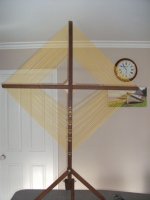
I'm Building a Part 15 AM Transmitter Antenna

cc333

Member
Joined
Nov 22, 2022
Messages
75
It's a 1/2 inch copper pipe about 10 feet long, and I'm running it at 1610 kHz.

I need to tune it for better effectiveness, but I'm a bit unsure as to how to do that.

I built a loading coil, but I have no idea what its inductance is (I ordered an LCR meter, so hopefully I can find out), but I'm wondering if maybe I can get by with a fixed 120 uH RF inductor and 7-150 pF variable capacitor instead. I'm not planning on varying the frequency much, pretty much just within 1600-1700 kHz.

Any thoughts, ideas or suggestions on this are appreciated!

c
 

prcguy

Member
Premium Subscriber
Joined
Jun 30, 2006
Messages
16,637
Location
So Cal - Richardson, TX - Tewksbury, MA
Go here and calculate the needed inductance based on diameter of coil and location along the whip.

Then you can go here to calculate the size and number of turns for the required inductance.

It would be good to have some variable inductance in the circuit to adjust resonance then I would tend to make a wide band matching transformer to go from 50 ohms to the really low impedance of the resulting whip, probably just a few ohms or less. The antenna will be extremely narrow band and you cant just guess and put together some parts, it would have to be tuned with an antenna analyzer or similar.

Or buy a used Hi-Q amateur 80-10m screwdriver antenna with 5" dia coil and stick a 5ft mast on top with very large capacity hat like six spokes and 8ft diameter. Mine will tune down to at least 1.5MHz and a 12.5 ohm to 50 ohm matching transformer seems to work well at those low frequencies.

You might want to read up on FCC part 15 transmitters as commercially made units must have a permanently attached antenna not to exceed a certain size and what is being discussed is probably not legal. For a home made system you might be able to use a larger antenna but you would be limited to a maximum signal level that is very small since the FCC rules say the distance is supposed to be about 200ft for what you want to do. At some point your no longer a part 15 transmitter and instead a low power AM broadcast station subject to licensing.
 
Last edited:

RFI-EMI-GUY

Member
Joined
Dec 22, 2013
Messages
7,503
The FCC has some weird obsession with respect to the ground counterpoise being part of the antenna radiator overall length so you are limited to the effective height. In other words, mounting it on a big metal pole is problematic.

Part 15 is a recipe for failure.
 

Echo4Thirty

Active Member
Premium Subscriber
Joined
Oct 6, 2021
Messages
904
Location
Spring,TX
Just save a few hundred bucks, you'll soon be able to buy a complete full service AM station...licensing is another animal, but they'll soon be available for fractions of pennies of a dollar.
For the station equipment, sure. They are dumping them off for the value of the land vs the value of income derived from on air. The trend in Houston is to now build master AM tower sites and multiplex the stations in, and sell off their old single use sites for the land,
 

cc333

Member
Joined
Nov 22, 2022
Messages
75
Just save a few hundred bucks, you'll soon be able to buy a complete full service AM station...licensing is another animal, but they'll soon be available for fractions of pennies of a dollar.
That would be ideal, but that's still a few years off, isn't it?

c
 

MTS2000des

5B2_BEE00 Czar
Joined
Jul 12, 2008
Messages
5,704
Location
Cobb County, GA Stadium Crime Zone
That would be ideal, but that's still a few years off, isn't it?

c
Dunno, around here all that remains are a few Korean stations and WSB. Some God Squad but most is simulcast on FM translators or moved to FM full service exclusively.

1010 WINS, one of the highest rated and pioneering all news stations in NYC is now on an FM big stick. 92.3, Howard Stern's old home. How ironic. The guy "who took a toilet bowl radio station to the top of the ratings" is dethroned for news/talk on his old dial position. But what does he care, he's making millions on his 20 year SXM contract.
 
Joined
Jun 13, 2018
Messages
869
Hi "C"

I am not quite sure what your purpose in building a low power BC band transmitter is. Is there an end purpose or just to experiment ??

If its an experiment, you may find that you are not alone -- I have known a few hams that have taken a (strange) pleasure in Part 15 BC Band transmitters and seeing just what they can achieve under some really severe restrictions. But fortunately the laws about this section of Part 15 were written Lonnnng ago and are quite easy for an experimenter to adhere to.

§ 15.219 Operation in the band 510–1705 kHz.

(a) The total input power to the final radio frequency stage (exclusive of filament or heater power)** shall not exceed 100 milliwatts.
(b) The total length of the transmission line, antenna and ground lead (if used) shall not exceed 3 meters.
(c) All emissions below 510 kHz or above 1705 kHz shall be attenuated at least 20 dB below the level of the unmodulated carrier. Determination of compliance with the 20 dB attenuation specification may be based on measurements at the intentional radiator's antenna output terminal unless the intentional radiator uses a permanently attached antenna, in which case compliance shall be deomonstrated by measuring the radiated emissions.


The fellows I know are all quite weird in their passion for these things radio-exotic (like my father)- but they've done some rather remarkable stuff under these challenges. (Why they just didn't do them in the 160 metre band is best left up to them to explain ;) .)


______________________________________________________________________________________________________

**you can tell this provision has not been updated in years when it refers to "filament or heater power :)

_____________________________________________________________________________________________________

That being said, choosing the right frequency in the BC band is paramount, but you are not restricted to any set 10 KHz standard broadcast channel. 1627 KHz is just fine, for example, if it puts you into the clear. And of course with the restrictions on antenna length you will want the high end of the band-- every little plus-- efficiency wise-- matters here.

With a top loaded 10 foot ("3 metre") antenna theses "BC'ers" fellows claim ranges measured in miles using simple homebrew'd double side transmitters
and communication-grade receivers.

Remember too, that experimental designed, home constructed transmitters are perfectly Part 15 legal and do not have the same restrictions as if they are for commercial sale.

Technically the whole secret revolves around that old bugger that has been the fore-front of radio since Marconi---the antenna.
Now you are in for a whole lot of neat experimenting--
The successful designs tend to be top loaded verticals. Forget anything less---we are after vertical radiation, even for these toy-power transmitters-- and even here we are after a groundwave that can not be achieved with a horizontal radiator.
Its going to be another challenge to calculated the value of a 'top loading coil'-- but the biggest in diameter and most turns you can construct, plus a generous capacity 'hat' is a starting point. At the base use an LC matching network-- use a big air variable capacitor--- connected directly from the transmitter to the vertical pole..... the 1/2 inch copper pipe is good, a larger diameter is even better. And you want to mount this over the best ground system you can achieve... the rules leaves that vague just so long as that connection is part of your 10 feet.

As far as adjusting this beauty, use a field strength meter set as far from the antenna as you can get reasonable readings. You'll want a very sensitive meter, and of course tune for the best field strength.
Forget any SWR meters-- the power is too low and with this transmitter-so-short antenna it would be like trying to measure the SWR of a Tesla coil. An antenna tuner will be too loss-y as well.
Go for a big coil and a quality air variable in a parallel LC matching circuit right at the antenna's
base.

___________________________________________________________________________________________________________


This sounds like a fun project, one filled with some great learning potential.
If you can make this successful you can do do anything radio.

I would love to hear an epilogue :)


Lauri

c8.jpg


.
 

cc333

Member
Joined
Nov 22, 2022
Messages
75
Thank you everyone for your input!

So, I got an LCR meter so I could measure the inductance of the coil I built, and it's only 16uH? Maybe I'm not reading it right? I got this one here: DM4070 3 1/2 Digital LCR meter w/self-discharge 2000uF USA Seller | eBay

Anyway, with that in mind, I used the calculators @prcguy linked to, and got a required inductance of almost three hundred uH. No wonder my coil doesn't seem to have any meaningful impact on anything!

So, can a variable air-core capacitor of, say, 7 to 150 pF compensate somewhat, or am I better off looking for/building a better coil?

I'm not looking for peak efficiency, but I wouldn't mind if I could do a bit better. As is, 100mW barely makes it to the other end of the house, and I'm in a small house!

As for grounding, I'm working on that. I don't really have any space for a proper counterpoise, so the best I can do is stick a rod into the ground. It's not much, but it's better than nothing I figure?

Although, I will note that I can actually get better range without grounding anything, which to me is odd, given how important a good ground seems to be.

c
 

majoco

Stirrer
Joined
Dec 25, 2008
Messages
4,315
Location
New Zealand
BC band DX'ers use tuned loops to pick up those weak signals - so would they work in reverse? Mine has a single turn to feed into a receiver - so if I feed a signal into that single turn would I get some enhanced signals further away? I feel an experiment coming on with a signal generator.....watch this space....
 

Attachments

  • loop for ARF.jpg
    loop for ARF.jpg
    51.3 KB · Views: 2

cc333

Member
Joined
Nov 22, 2022
Messages
75
@majoco I actually tried connecting my transmitter to an AN-100 tunable loop receiving antenna, and it puts out a respectable signal that covers most of the house... if I set the Tx power to 600mW (100mW is almost useless).

I'd imagine that, if properly tuned, one of those DIY loops would work quite well.

c
 
Joined
Jun 13, 2018
Messages
869
Well C, measuring the inductance of what I am assuming is the power output stage of your transmitter may be insightful, but without knowing what this inductor is doesn't help much. Is it a small, tight wound little thing over a ferrite core, or is is a bigger coil over, say, a ceramic form ?
You are going to want something along the lines the later.

True, you are building a transmitter that is only 100 milliwatts, but you want to build it as if it were a 100 Watts. You want a real LC tunable
stage here-- a real coil and a air variable capacitor with some value.

I'd start with a piece of 1" PVC tubing as the core's foundation. Close wind 100 or so turns of #16 enamel wire on it. Parallel this with a 10 to ~500 mmf air variable***.

With a field strength meter tune this output stage for maximum... and with this coil --and probably in the mid range on the capacitor --you should hit resonance for 1600-1700KHz's. If not, rewind the coil (add or subtract) turns as necessary. If you have access to an old designer's friend-- a "GDO" (Grid Dip Oscillator) ---you instantly can see what the resonance frequency of this LC circuit is.

-------------------------

You have to think this thru big-scale. If it stays a toy construction it will perform like a toy.
Maybe that is all you want, but---------------------------------------

Thinking big goes equally for all parts of this system,, for the ground, antenna and the choice of modulation are all part of this transmitter's matrix.

002(2)a.jpg

t would be helpful if you have a schematic to download here,
..........but anyway--Good Luck to you !!

Lauri


.
________________________________________________________________________________________________________

**the last time I used "mmf's" value in these forums it showed my vintage.... you may have to convert that. These variable capacitors are find-able however--- old tube broadcast AM radios all had them..)

.
 
Last edited:

cc333

Member
Joined
Nov 22, 2022
Messages
75
OK, with the 120uH RF inductor and 7-150pF variable capacitor, I seem to be making some progress!

With just the 10 foot pipe and nothing else, I can get a range of almost 1/4-1/2 a mile on the same power (600mW) that barely reached into the yard with the old coil I made.

That being said, I'd like to maximize the power output (field strength?) so I can have a similar range at the legal 100mW, and for that, I think I need a field strength meter. Can anyone recommend a cheap one that works at 530-1710 kHz and less than 1W?

Then, I'll work on grounding (although I'm quite impressed with it as is!)

c
 

prcguy

Member
Premium Subscriber
Joined
Jun 30, 2006
Messages
16,637
Location
So Cal - Richardson, TX - Tewksbury, MA
OK, with the 120uH RF inductor and 7-150pF variable capacitor, I seem to be making some progress!

With just the 10 foot pipe and nothing else, I can get a range of almost 1/4-1/2 a mile on the same power (600mW) that barely reached into the yard with the old coil I made.

That being said, I'd like to maximize the power output (field strength?) so I can have a similar range at the legal 100mW, and for that, I think I need a field strength meter. Can anyone recommend a cheap one that works at 530-1710 kHz and less than 1W?

Then, I'll work on grounding (although I'm quite impressed with it as is!)

c
I think you will be much better off with an antenna analyzer that covers the frequency range your playing with and about a 4:1 RF transformer to go from 50 ohms to 12.5 ohms to start with and probably lower. A short loaded 1/4 wave antenna will be less than 50 ohms at resonance and you are at the extreme range of this trying to get a 10ft antenna to work at 1.7MHz or lower.

With a broad band matching transformer all you will need is a loading coil on the antenna and a capacity hat would be nice. There are programs that will tell you the best place for the loading coil (usually about the middle but in this case maybe at the top) and with the matching transformer you just need the right inductance to resonate a 1/4 wave loaded antenna and an antenna analyzer will tell you what frequency its working at with a given coil. I would make a fixed loading coil to get you to the higher end of where you want to be then get an adjustable roller inductor off eBay to do the final field tuning or to help if changing frequencies.
 
Joined
Jun 13, 2018
Messages
869
600 milliwatts ?

Sorry to say this cowboy, but you are already exceeding the maximum legal power limits by half a watt.
I seriously doubt it is going to cause much of a blip on any official's radar, but you are now operating illegally.

You may plead the provision of an intentional radiator's field density in the 490-1705 KHz range-- that's 24000 microvolts divided by frequency in KHz's at 100 feet.... but I seriously doubt your ability to measure that figure.

.
 

cc333

Member
Joined
Nov 22, 2022
Messages
75
I know.

Honestly, the antenna was so inefficient that 600mW barely made it outside the house, so I didn't figure that legality was much of a problem.

Of course, the antenna is much more efficient now, so I'll have to turn the power down to 100mW. Even so, it still probably won't make much of a dent in anyone's monitoring efforts (my efforts are like a faint whisper in a noisy crowd).

You may plead the provision of an intentional radiator's field density in the 490-1705 KHz range-- that's 24000 microvolts divided by frequency in KHz's at 100 feet.... but I seriously doubt your ability to measure that figure.
Yeah. I'm using that as a goal since if I can get close to that, I would hopefully be able to get decent range at the legal 100mW. I can't measure it exactly of course, but I should be able to approximate it.

c
 
Top