Maco M105C QUESTIONS

Humblehero666

Member
Joined
Oct 28, 2020
Messages
35
I have a MACO M105C as I mentioned here. I have 5 Elements with a 26' beam. It's constructed out of aluminum. I have a fifty foot piece of coax going into the radio.
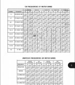
The question is how can I get 28.35 10 meters?

The instructions only give different options so I'm trying to tune it to this frequency.

I have using a LDG Z PLUS to tune.
I am using a ASTATIC PDC1 swr meter.
Iam Using a yaesu ft840 with a yaesu md-1 mic.

Any help is appreciated. I just got my license not to long ago. I have been studying for a general and plan on ordering a book on structure of antennas.

Thanks in advance '73 from KC1PNR!!!
 

prcguy

Member
Premium Subscriber
Joined
Jun 30, 2006
Messages
16,048
Location
So Cal - Richardson, TX - Tewksbury, MA
One method I've used to make a minor change freq on a Yagi is calculate the difference between the frequency its tuned to now and where you want to go. For example the MACO might be centered around 27.200 now and a 1/4 wavelength in free space is 8.602ft. A 1/4 wave at 28.35 is 8.253ft and the difference between the two is .348 ft. If you were to shorten all elements by .348ft it should be very close.

If you calculate so the answer is in CM or MM it might be easier to measure than 10ths of a foot.
 

Humblehero666

Member
Joined
Oct 28, 2020
Messages
35
Screenshot_20230514_184038_Adobe Acrobat.jpg
This is wat I found online. Being a tech the only freq I can use is 28.3 - 28.5 so I don't have much room for error. I did assemble it alone and set all the other equipment up alone. I jist need help figuring out the measurements.

So far I've shrunk the driven element 1 inch in each side. No change in RX OR TX.
 

Attachments

  • Screenshot_20230514_184038_Adobe Acrobat.jpg
    Screenshot_20230514_184038_Adobe Acrobat.jpg
    151.7 KB · Views: 7

Humblehero666

Member
Joined
Oct 28, 2020
Messages
35
I've been trying for a week. Made one contact solid. But the rest were static and garbled. I have to work on the element distance and lengthe one more time.
 

prcguy

Member
Premium Subscriber
Joined
Jun 30, 2006
Messages
16,048
Location
So Cal - Richardson, TX - Tewksbury, MA
View attachment 141824
This is wat I found online. Being a tech the only freq I can use is 28.3 - 28.5 so I don't have much room for error. I did assemble it alone and set all the other equipment up alone. I jist need help figuring out the measurements.

So far I've shrunk the driven element 1 inch in each side. No change in RX OR TX.
You can't just change the driven element, the entire antenna has to change with a frequency shift that far otherwise all the gain figures are out the window. From my rough calculation all elements would have to be shortened about 4" (each side of the dipoles) to get in the ball park.
 
Last edited:

Humblehero666

Member
Joined
Oct 28, 2020
Messages
35
Ok im in the process of finding a calculator or the formula to do this. The instructions are limited. The antenna also has a gamma match but has lines drawn on the pole to slide it up with no numbers. The goal is to figure this out before I raise it up. @prcguy
 
Last edited:

prcguy

Member
Premium Subscriber
Joined
Jun 30, 2006
Messages
16,048
Location
So Cal - Richardson, TX - Tewksbury, MA
Ok im in the process of finding a calculator or the formula to do this. The instructions are limited. The antenna also has a gamma match but has lines drawn on the pole to slide it up with no numbers. The goal is to figure this out before I raise it up. @prcguy
Since there are posted dimensions for 28.1 and 28.6MHz, just split the difference and make all elements the calculated lengths for that. For example, the reflector B dimension is 69" for 28.1MHz and 67" for 28.6MHz so make it 68" for 28.35MHz. Do the same calculation for all elements. Then you adjust the gamma match for best VSWR.
 

Humblehero666

Member
Joined
Oct 28, 2020
Messages
35
Set up and fully corrected the antenna how ever np one on ten that I can reach bummer....

Ordered the digrig and cables to hook to pc.
 

K7MEM

Member
Joined
Dec 16, 2013
Messages
432
Location
Swartz Creek, Michigan
What times were you on the air? 10 Meters is effectively a daylight band. The best time is late afternoon, or early evening, before the sun goes down. Once the sun goes down you won't hear anything. It is currently a good time for 10 Meter propagation, but it doesn't seem to be consistent. Like any other band, you just need patience.

Of course, as a Tech, you are allowed CW, RTTY, and Data privileges from 28.0 to 28.3 MHz (200 Watts Max). But, the propagation is pretty much the same for those modes. Or, to get more SSB space on 10 Meters, just go test for General. It's really not that difficult and opens up so much more space.
 

Humblehero666

Member
Joined
Oct 28, 2020
Messages
35
That sounds like one of the issues. I usually do 7 - 10 pm on and off. I'm adding a digrig to this setup hopefully it will help a little. Testing on the 29th of june!
 

Humblehero666

Member
Joined
Oct 28, 2020
Messages
35
Update got the dig rig doesn't work on the yaseu ft840 with the 8xx brand cable.

Test was in June not may.

Advice was to point the antenna straight up at the sky with the reflector on ground.
 

K7MEM

Member
Joined
Dec 16, 2013
Messages
432
Location
Swartz Creek, Michigan
Update got the dig rig doesn't work on the yaseu ft840 with the 8xx brand cable.
Easy home brew or buy one?

Yes, one look at that cable told me it wouldn't work. I looked through all the other cables available at Digrig and none of them will work for the FT-840. The CAT connector might work, but the audio needs to be taken from the Mic connector in front and the RCA jack in the back. It is possible to make your own cable. There are about a dozen schematics for CAT and Audio interfaces on the internet. Right in Digrig's own forum is a brief discussion on the FT-840 and how the "8xx" cable kit doesn't work. In that discussion are several drawings for interfaces. However, two of them seem to be for use with a different style interface.

I made the digital interface for my IC-735 about 20 years ago and it still works fine. For ICOM, CAT or Rig control is called CI-V but is essentially the same thing. I use a USB to Serial Port converter cable (FTDI) and then a home brew RS-232 to TTL level converter on a Windows 10 desktop. I use a separate USB to Serial Port converter cable to manage PTT and direct CW Keying. The Audio In and Out come directly out of the PC and connect directly to an Accessory connector on the rear of the IC-735. Many will insist on transformer isolation, but I have never had any issues.

For software, I use an old version of Ham Radio Deluxe (V5.24.38). HRD offers a 30 day trial for their latest version (6.xx) from their web site. However, while HRD handles a lot of different digital modes FT8 is not one of them. There are several other software available, like Fldigi. Fldigi is completely free, but has some differences from HRD. For example, Fldigi does not have Direct CW Keying. Whereas, HRD does, through the same port as PTT.

However, switching to digital modes is not a quick fix for making a contact on 10 Meters. You just need to get on at the right time when conditions are good. Patience, patience, patience. During one of the previous solar cycles, I had a Radio Shack HTX-100 in my car with a 3' mag mount vertical on the trunk. I could never make any contacts in the morning, on my way to work. But around 4:00 PM, the conditions were great. I could easily talk cross country with only 5 watts. You may want to move up your operating times a bit.
 

Humblehero666

Member
Joined
Oct 28, 2020
Messages
35
Yes, one look at that cable told me it wouldn't work. I looked through all the other cables available at Digrig and none of them will work for the FT-840. The CAT connector might work, but the audio needs to be taken from the Mic connector in front and the RCA jack in the back. It is possible to make your own cable. There are about a dozen schematics for CAT and Audio interfaces on the internet. Right in Digrig's own forum is a brief discussion on the FT-840 and how the "8xx" cable kit doesn't work. In that discussion are several drawings for interfaces. However, two of them seem to be for use with a different style interface.

I made the digital interface for my IC-735 about 20 years ago and it still works fine. For ICOM, CAT or Rig control is called CI-V but is essentially the same thing. I use a USB to Serial Port converter cable (FTDI) and then a home brew RS-232 to TTL level converter on a Windows 10 desktop. I use a separate USB to Serial Port converter cable to manage PTT and direct CW Keying. The Audio In and Out come directly out of the PC and connect directly to an Accessory connector on the rear of the IC-735. Many will insist on transformer isolation, but I have never had any issues.

For software, I use an old version of Ham Radio Deluxe (V5.24.38). HRD offers a 30 day trial for their latest version (6.xx) from their web site. However, while HRD handles a lot of different digital modes FT8 is not one of them. There are several other software available, like Fldigi. Fldigi is completely free, but has some differences from HRD. For example, Fldigi does not have Direct CW Keying. Whereas, HRD does, through the same port as PTT.

However, switching to digital modes is not a quick fix for making a contact on 10 Meters. You just need to get on at the right time when conditions are good. Patience, patience, patience. During one of the previous solar cycles, I had a Radio Shack HTX-100 in my car with a 3' mag mount vertical on the trunk. I could never make any contacts in the morning, on my way to work. But around 4:00 PM, the conditions were great. I could easily talk cross country with only 5 watts. You may want to move up your operating times a bit.
I appreciate your reply. Patience is not my strong suit. But I'm learning. Last night I made a 10m dipole in about 15 minds but 10 wasn't hoping for me. Will try again today afternoon thanks!
 

K7MEM

Member
Joined
Dec 16, 2013
Messages
432
Location
Swartz Creek, Michigan
Here is another suggestion for quickly checking the band(s). You might want to try the NA5B WebSDR Receiver. I know you are located in MA. I am located in MI and use the SDR to check the bands. It's nice when you just want to listen and don't want to fire everything up. The one I listed is in the Washington DC area. However, there are several others that might be nearer to you.

Looking at 10 Meters right now, 1:02 PM local (5:02 PM Z), and find it is completely dead. I heard one SSB station from Australia around 28.444 MHz, but he disappeared quickly. Lower down, on 11 Meters, it is a bit more active, but not much. Very poor audio. As I type this, I am listening to a couple of SSB stations on 7.175 MHz. Very good audio. I think they were both in NJ. Of course, they are both running 1KW, so they should sound good. There were also a couple of CW stations that were very easy to copy.

Good luck.
 
Top