Mini yagi for 2-meter fox hunting

Status
Not open for further replies.

PickyBiker

Member
Joined
Nov 4, 2022
Messages
8
I just went to a 2-meter walking fox hunt with a local HAM Radio Club. Most hunters used a 1/2 wave 3 element Yagi for hunting. A few were home brew, and some purchased. On a walking hunt, we didn't really need the gain a Yagi provides, in fact we needed to attenuate the signal as we neared the target. The important thing in a fox hunt like this is antenna directivity, rather than gain.

I wonder if it is possible to build a smaller yagi (1/4 wave) that wouldn't have much gain but would still be directional in the 2-meter band. That would seem to be usable in walking hunts and in a driving hunt when you get closer to the target.

If not a smaller Yagi, is there another small directional antenna design that can be used? I know about TDOA and Doppler antennas, but what I would like to find is a simple small handheld directional antenna.
 
Joined
Jun 13, 2018
Messages
869
I think you certainly can scale down a directional 2 metre antenna, Picky.

How do you do it ?..... well, may I suggest this would be a fun experimental project--- if you have a 2 metre signal source like a repeater, or even the NOAA weather broadcasts, I would start there. Design/build a few models and see how they work against these signals. Remember, you are looking only at receiving so things like transmit SWR are not important. Personally I envision a loop of some sort.

You may come up with an impressive antenna for your next fox hunt; impress your friends!!...and, a plus-- learning a bit about direction antennas.

Good hunting there Cowboy !! :)


Lauri

Lauri.jpg

.
 

KE5MC

Member
Premium Subscriber
Joined
Dec 19, 2002
Messages
1,242
Location
Lewisville, TX
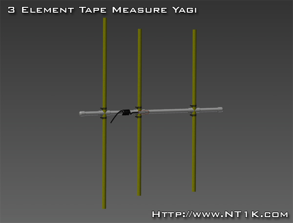
The typical 3 element retractable tape measure antenna has a deep null on the back side for closer in work. The well equipped 'hound' will have a switch box or offset attenuator. The offset is a little pricy, but time and money to make switch box I think is offset with the simplicity of using the offset. The tape measure antenna is common and you should have seen one at the hunt. Did you notice anyone using the null side of the antenna?
Google search for ham fox hunts will give you hours of reading.

Arrow offset attenuator link...

Mike

P.S. found link for tape measure antenna.
 
Last edited:

Mikejo

Member
Joined
Jul 18, 2007
Messages
234
Location
Waltham,MA
I don’t know if this would help but of course, you know the third harmonic of the frequency for most Foxhunts, 146.565 is. 439.695 still within most HT’s frequency range range (as mentioned above, that would not matter much because you’re on receive only).

You could possibly just try using a small UHF Yagi tuned for that frequency, I don’t know how well it would work if you were to try the UHF Yagi on the on 146.565 on the Fox VHF frequency, but perhaps just using a UHF Yagi on the third harmonic might do the trick for you!

Just my two cents; experiment. Have fun, it’s the best part of the hobby, I think!
 

mmckenna

I ♥ Ø
Joined
Jul 27, 2005
Messages
25,033
Location
United States
A few years back I had to chase down some interference to one of our UHF repeater inputs. The 3 element tape measure antenna worked well, as I couldn't get anything else delivered fast enough. I made it with one of the "free" harbor freight tape measures and some scrap PVC pipe I had around. Took some trial and error, but eventually got it working well enough to walk right up to the offending transmitter.

Nice thing about the tape measure elements is that they are flexible and won't break.

And I agree with Ms. Frostbite, a loop might be a good option.
Don't forget that you can use body shielding as an option.
 

KB4MSZ

Billy
Premium Subscriber
Joined
Mar 12, 2018
Messages
972
Location
Tampa, Florida
I can't see how this could ever be very effective. Even if you could manage to get close to one you would need an awful lot of power to stop him.
 

MUTNAV

Active Member
Premium Subscriber
Joined
Jul 27, 2018
Messages
1,297
I can't see how this could ever be very effective. Even if you could manage to get close to one you would need an awful lot of power to stop him.
You forgot the "bazinga" or whatever emoji it is for laughing... :)
 

AK9R

Lead Wiki Manager and almost an Awesome Moderator
Super Moderator
Joined
Jul 18, 2004
Messages
9,883
Location
Central Indiana
The tape-measure Yagi is pretty much standard for walking fox hunts. Yes, you need an attenuator to deal with close-in foxes. Assuming the fox is on 2m, tuning your receiver to the 3rd harmonic (for example, 146.490 MHz x 3 = 439.47 MHz) can get you a usable signal that is heavily attenuated.

A halo vertical loop would have less gain than the Yagi while still having some directivity. Just remember that a halo vertical loop will "peak" on a signal in two opposite directions.
 
Last edited:
Joined
Jun 13, 2018
Messages
869
.

I like to think of myself as an historian. Whenever something 'new' is brought up I will delve into what history's proceed'd it-- and radio is full of passed lessons I learn from.

One easy place to begin is viewing all the WW2 training films-- and if I don't find something I didn't know already (which isn't rare) - these films are very entertaining.
My grandfather who flew in B24's during the Second World War told me of how they would DF a station with loop antennas (which had two major lobes) --by changing course and noting the new lobe's headings. This way they could tell if they were flying towards or away from the station. Want a little mental gymnastics, try that one out.
If you really are curious about how life-and-death this simple maneuver can be, Google the tale of the "Lady Be Good" and what happen'd to her and her crew.

If nothing else, this Direction Finding film will transport you back to a simpler era- one no less complex to those that were there, but quaint to us as seen thru our lens of time :)


Lauri

.[/MEDIA]
 

prcguy

Member
Premium Subscriber
Joined
Jun 30, 2006
Messages
16,213
Location
So Cal - Richardson, TX - Tewksbury, MA
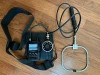
Here is part of my current DF setup. I would be bouncing between a 3 element Yagi for VHF or a 7 element for UHF then going to the loop for close in work.

As far as making a 2m Yagi smaller, directionality goes hand in hand with gain and gain goes hand in hand with boom length. Bigger is better and there is no good way to make a simple Yagi smaller and keep the same gain, beamwidth and F/B ratio. A small Yagi is going to have a huge beamwidth and you end up pointing it all over the place, finding two degraded points about the same level then splitting the difference to find the best center point.

A loop on the other hand works by nulling and where a 3 element Yagi might have a 3dB beamwidth of 60-75 degrees (guessing at the moment) a small loop can have a useable null thats well under 10 degrees wide and usually smaller. They will give you a much more accurate heading to the transmitter at a cost of much less gain.

The setup below is a Yaesu FT3 something that covers almost DC to 1GHz AM and FM. Then there is a 70dB step attenuator and a VHF/UHF loop from Arrow Antennas. All coax is double shield silver plated RG-223. There is also a ferrite common mode choke at the antenna to decouple it from the feedline to help preserve directionality. The radio and step attenuator are mounted to a Delrin plate and the radio is held down with miniature bungee cord and there is a neck strap so it all sits nicely at chest level and keeps a hand free for antenna pointing.

1680657860444.jpeg
 

MUTNAV

Active Member
Premium Subscriber
Joined
Jul 27, 2018
Messages
1,297
.

I like to think of myself as an historian. Whenever something 'new' is brought up I will delve into what history's proceed'd it-- and radio is full of passed lessons I learn from.

One easy place to begin is viewing all the WW2 training films-- and if I don't find something I didn't know already (which isn't rare) - these films are very entertaining.
My grandfather who flew in B24's during the Second World War told me of how they would DF a station with loop antennas (which had two major lobes) --by changing course and noting the new lobe's headings. This way they could tell if they were flying towards or away from the station. Want a little mental gymnastics, try that one out.
If you really are curious about how life-and-death this simple maneuver can be, Google the tale of the "Lady Be Good" and what happen'd to her and her crew.

If nothing else, this Direction Finding film will transport you back to a simpler era- one no less complex to those that were there, but quaint to us as seen thru our lens of time :)


Lauri

.[/MEDIA]
Cute video, I like the primitive simulators/training aids they used, and the apparent lack of access to a tripod.

The A/N arrangement was a little new to me, but the loop antenna is what is/was used on boats a lot, to the the point that they had digital displays for frequency.

If I remember right, the WW 2 fighters that were lost in the Bermuda triangle, were suspected to have fallen prey to the loops ambiguity (or reading a compasses wrong).


The fan shaped markers were interesting (at UHF (75Mhz)) :) , I have to wonder if this was the origin of the satellite tracking fan shaped beam, a "space fence",

I saw the part of it that was in Gila AZ, wondering what the navy was doing there. It was basically a very large marker beacon array, used as a kind of a radar, I don't know how useful it is with all of the junk in orbit now, but long ago, its data, when combined with others, could detect new satellites and figure out orbital elements.


SpaceFence2_FP4X3.jpg


They are making (have made) a newer version.


Thanks
Joel
 

nd5y

Member
Joined
Dec 19, 2002
Messages
11,650
Location
Wichita Falls, TX
The space fence sites in AZ and AL were fill-in sites for low altitude objects over the E and W coasts.
They each had one antenna bay. I don't know how many antennas or the power output or if they used the exact same equipment as the main site. They operated on offset frequencies (216.97 and 216.99 MHz) from the main site (216.98 MHz).

I worked at the main transmit site here in TX about 30 years ago. It had 17 bays with 144 antennas and one bay (that was split by a road) with 108 antennas. Each antenna had a 300 W amp. The total power to the antennas was 766.8 kW on 216.98 MHz. I don't know what the ERP was but migrating ducks and geese didn't like it.

The other half of the system was the six receive sites in CA, NM, AR, MS and two in GA. I know almost nothing about them.
 
Last edited:

vagrant

ker-muhj-uhn
Premium Subscriber
Joined
Nov 19, 2005
Messages
3,381
Location
California
@prcguy - Does that step attenuator in the photo cost about double of the radio? I figure you found/bought it for $1.55 on eBay. Ahhh…I need to search more often.

I too am a fan of third harmonic and tuning slightly off freq when close.
 

prcguy

Member
Premium Subscriber
Joined
Jun 30, 2006
Messages
16,213
Location
So Cal - Richardson, TX - Tewksbury, MA
@prcguy - Does that step attenuator in the photo cost about double of the radio? I figure you found/bought it for $1.55 on eBay. Ahhh…I need to search more often.

I too am a fan of third harmonic and tuning slightly off freq when close.
I think that is a Dayton Hamstervention buy, I would not have spent more than about $30 on it.
 

majoco

Stirrer
Joined
Dec 25, 2008
Messages
4,315
Location
New Zealand
The DF on ships I sailed on was rarely used, but the best indication of the signal's bearing was given by the null, not the peak in strength. The same principle was used on aircraft to determine the bearing of an NDB. Both systems used a loop antenna and to resolve the 180degree ambiguity a 'sense' antenna signal was added to the 'figure of eight' loop. When the amplitude of the sense signal was correctly adjusted, the resultant pattern was a cardiod (heart shaped) with a sharp null to point at the station.
 

iMONITOR

Silent Key
Premium Subscriber
Joined
Sep 20, 2006
Messages
11,156
Location
S.E. Michigan
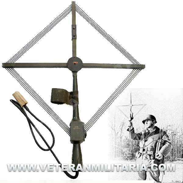
I bought one of these brand new when I was about 15 years old. I think I paid $20. Wished I would have kept it!

original-us-homing-modification-kit-mc-619.jpg
 
Status
Not open for further replies.
Top