• To anyone looking to acquire commercial radio programming software:

    Please do not make requests for copies of radio programming software which is sold (or was sold) by the manufacturer for any monetary value. All requests will be deleted and a forum infraction issued. Making a request such as this is attempting to engage in software piracy and this forum cannot be involved or associated with this activity. The same goes for any private transaction via Private Message. Even if you attempt to engage in this activity in PM's we will still enforce the forum rules. Your PM's are not private and the administration has the right to read them if there's a hint to criminal activity.

    If you are having trouble legally obtaining software please state so. We do not want any hurt feelings when your vague post is mistaken for a free request. It is YOUR responsibility to properly word your request.

    To obtain Motorola software see the Sticky in the Motorola forum.

    The various other vendors often permit their dealers to sell the software online (i.e., Kenwood). Please use Google or some other search engine to find a dealer that sells the software. Typically each series or individual radio requires its own software package. Often the Kenwood software is less than $100 so don't be a cheapskate; just purchase it.

    For M/A Com/Harris/GE, etc: there are two software packages that program all current and past radios. One package is for conventional programming and the other for trunked programming. The trunked package is in upwards of $2,500. The conventional package is more reasonable though is still several hundred dollars. The benefit is you do not need multiple versions for each radio (unlike Motorola).

    This is a large and very visible forum. We cannot jeopardize the ability to provide the RadioReference services by allowing this activity to occur. Please respect this.

Mod chip IC-F320s

Status
Not open for further replies.

thesavo

Member
Feed Provider
Joined
Nov 8, 2019
Messages
160
Location
Schenectady, NY
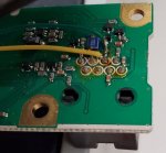
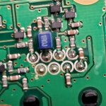
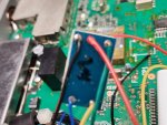
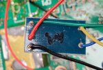
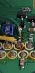
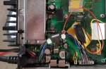
I brought a FOR PARTS F320s unit to use for a Broacastify feeds or as parts for my other one if it was that bad. I took it part to clean it up and found what I would think of as a mod chip for a game console. It is wrapped in shrink tube and I have not cut it part. Has any one see something like this before?

The chip has 5 wires and they seem to have the below listed connections. I still have to take the front cover off to see where two of them go. It just seems to odd.

What are your thoughts?
Mod chip wire colors
blue - cut off opc-617 out of radio
Yellow - To front panel of radio
green - to front panel of radio
Black - X2 Presumed ground
Red - IC9 - Presume 5V


Blue from OPC-617 seems to leave the radio out the normal accessory cable. It would seem by looking at the pinout that the blue wire is intended to Dimmer for the front panel. I would guess that this may be used to control the brightness of front panel or to control glyfs on the display itself.

1631552000295.png

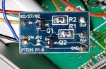
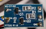
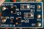
Update: I did cut off the shrink tube and has there ever been hardware mod to disable Push-to-talk?
it has the following text

PTTDIS R1.0
02/27/02 - 2002 build presumed

The wire colors have the following labels
blue - disable
Yellow - IN
green - Out
Black -Gnd
Red - Vcc

first guess - Dimmer control
second guess - PTT disable
 

Attachments

  • 20210913_122411.jpg
    20210913_122411.jpg
    153 KB · Views: 27
  • 20210913_131231.jpg
    20210913_131231.jpg
    165.1 KB · Views: 25
Last edited:

thesavo

Member
Feed Provider
Joined
Nov 8, 2019
Messages
160
Location
Schenectady, NY
2nd guess may be closer. the following two wires go to PTT circuits in the control panel.
Yellow - PTT on the mic pin
Green - Junction of the resistor and Diode on the other side of the PTT

1631557910097.png
I added an image of the front panel of this radio and another without the modification

I presume that the modification allows the blue wire to trigger PTT allowance. If the blue wire is in the enable state, PTT from the mic jumps from the yellow though the modchip to the green and the circuit works as normal.

Any thoughts?
 

Attachments

  • 20210913_134333.jpg
    20210913_134333.jpg
    85.4 KB · Views: 10
  • 20210913_140734.jpg
    20210913_140734.jpg
    112.5 KB · Views: 10
Last edited:

thesavo

Member
Feed Provider
Joined
Nov 8, 2019
Messages
160
Location
Schenectady, NY
Hi mmckenna. Thanks for chiming in.
There are only solder points for the wires on the reverse side.
 

Attachments

  • 20210913_170727.jpg
    20210913_170727.jpg
    122.3 KB · Views: 16

mmckenna

I ♥ Ø
Joined
Jul 27, 2005
Messages
23,857
Location
Roaming the Intermountain West
OK, thanks.

Well, for the PTT function to work like you suggest, the trace would need to be cut somewhere to bypass the normal PTT circuit.

I was thinking it was some sort of radio ID device that triggered when the PTT was pushed, but I'd expect to see a chip on there that would be programmed with the radio ID.


Maybe someone else knows what it is.
 

a417

Active Member
Joined
Mar 14, 2004
Messages
4,669
can you get better pics of the front and back of that add-on board?
 

a417

Active Member
Joined
Mar 14, 2004
Messages
4,669
Ya. That's the best I can get with auto focus on my note 10.
Can you try to take the pic the same way you did of the mainboard? If you get too close you will quickly run into the near field of that camera, and it will look blurry. If you back up a couple of inches and not try to fill the screen with the chip you will get a sharper pic that can be blown up better on a screen.
 

thesavo

Member
Feed Provider
Joined
Nov 8, 2019
Messages
160
Location
Schenectady, NY
Can you try to take the pic the same way you did of the mainboard? If you get too close you will quickly run into the near field of that camera, and it will look blurry. If you back up a couple of inches and not try to fill the screen with the chip you will get a sharper pic that can be blown up better on a screen.
@a417 How about this take? I'd say the back has no traces.

It is very difficult to make out what the transistors are labeled.

The last image has the best view of their lids.
 

Attachments

  • 20210914_161104.jpg
    20210914_161104.jpg
    118 KB · Views: 18
  • 20210914_160954.jpg
    20210914_160954.jpg
    113.2 KB · Views: 19
  • 20210914_161825.jpg
    20210914_161825.jpg
    115.7 KB · Views: 16
Last edited:

mmckenna

I ♥ Ø
Joined
Jul 27, 2005
Messages
23,857
Location
Roaming the Intermountain West
OH, I think this might be used to trigger something when the PTT button is pressed, or to remotely disable transmit. Looks like the blue wire would have fed out of the radio to do something when the PTT button was pressed, or interrupted the PTT button, but that would have required a trace to be cut on the circuit board.

Might have been something as simple as muting an AM/FM radio when transmitting, or something that prevented the radio from transmitting when something else was going on.
 

a417

Active Member
Joined
Mar 14, 2004
Messages
4,669
OH, I think this might be used to trigger something when the PTT button is pressed, or to remotely disable transmit. Looks like the blue wire would have fed out of the radio to do something when the PTT button was pressed, or interrupted the PTT button, but that would have required a trace to be cut on the circuit board.

Might have been something as simple as muting an AM/FM radio when transmitting, or something that prevented the radio from transmitting when something else was going on.
I agree, I think we are somewhere in that ballpark. Judging by that unpopulated JP2, this appears to be a device that has several roles. Interesting.
 

thesavo

Member
Feed Provider
Joined
Nov 8, 2019
Messages
160
Location
Schenectady, NY
I think they may have cut the smt resistor on the PTT line on the front panel. . The solder job is rather crude and difficult to photograph.
 

Attachments

  • Screenshot_20210914-190449_Gallery.jpg
    Screenshot_20210914-190449_Gallery.jpg
    47 KB · Views: 10

thesavo

Member
Feed Provider
Joined
Nov 8, 2019
Messages
160
Location
Schenectady, NY
Thanks for the input everyone. I'm not knowledgeable enough to know if those conditions or outcomes are possible. I'll be using this as a feed radio and will inhibit tx in software. I think clipping the green wire on the radio side will label it as such.
 

thesavo

Member
Feed Provider
Joined
Nov 8, 2019
Messages
160
Location
Schenectady, NY
I finally got the unit setup to read the config. I checked the entire Radio Reference database for these frequency pairs. I am not sure who was the user prior to the seller on eBay.

ch1 rx 154.505
ch1 tx 159.93
no tone
0 results for this a pair

ch2 RX 152.27
ch2 TX 157.53
tone RX/TX 743n
86 results for this a pair - None found using this Tone
82 In/out match. 4 reverse match
 

Attachments

  • Screenshot_20210915-120933_Gallery.jpg
    Screenshot_20210915-120933_Gallery.jpg
    115.3 KB · Views: 9
Last edited:
Status
Not open for further replies.
Top