OCFD Question

Status
Not open for further replies.

K8BBL

Member
Joined
Feb 4, 2021
Messages
30
Location
Hazelton, WV
I currently use an OCFD split 78%/22%. It has a 4:1 dual core banun and 1:1 choke built into a tube and attached where the 2 legs come together at the tree top. The balun/choke assembly is high in the tree. Coax attaches there and runs down the tree and into the house. It works very well for 80/40/20/10.
I would like to move the balun assembly down the tree to a reachable point (without needing to climb up or lower the system). 2 questions: 1) If I do, does the distance between the balun and the attachment to the tree count as part of the leg lengths? In other words, do I now measure my legs (which are approx 104' & 28') starting at the balun, up the tree then the horizontal run? 2) If this distance counts as part of the leg length, what will the new legs, which now have a 90° bend in them, do to reception?
Option #2: put a simple dipole attachment with a 239 connector up top, run down the tree to the balun/choke assembly in coax & into the house from there. I was told this will work and the length of coax that goes down the tree will have no effect on the legs (but I'm no antenna whiz).
Or am I best off to simply leave the balun/choke assembly at the treetop?
Any suggestions, or comments on what not to do, appreciated.
 

prcguy

Member
Joined
Jun 30, 2006
Messages
15,360
Location
So Cal - Richardson, TX - Tewksbury, MA
MyAntennas makes the best OCFDs I've found and they use a 19/81% tap point which gives a useable match on all bands including 30, 17 and 12m without a tuner. One leg of my MyAntennas 80m OCFD is only about 25ft long but I love this thing where I can connect my amplifier and transmit on any amateur band 80 through 10 without a tuner.

There is always a problem with an OCFD on 80m because 80 is not harmonically related to any other band and they resonate around 3.55MHz but that can be easily fixed, or you just buy the MyAntennas 75m version that has the mod. Otherwise the tap point is very critical and moving it will affect something and usually in a bad way.

I'm not completely understanding your description but I can say you do not want to remote the 4:1 balun from the wire legs via coax. The leg lengths are simply the amount of wire sticking out each side of the 4:1 balun and you can bend them anywhere to some extent and consider it an inverted V, but I would not go more than a 90deg bend.

Also, there is a very specific balun recommended for OCFDs and very few mfrs use them. The balun will have two toroid cores side by side where the coax splits to each core and the two individual outputs to the antenna wires will come off each core. This type has an inherent high common mode rejection and most any other type will light up the coax with RF where the coax will be a radiating part of the antenna.


I currently use an OCFD split 78%/22%. It has a 4:1 dual core banun and 1:1 choke built into a tube and attached where the 2 legs come together at the tree top. The balun/choke assembly is high in the tree. Coax attaches there and runs down the tree and into the house. It works very well for 80/40/20/10.
I would like to move the balun assembly down the tree to a reachable point (without needing to climb up or lower the system). 2 questions: 1) If I do, does the distance between the balun and the attachment to the tree count as part of the leg lengths? In other words, do I now measure my legs (which are approx 104' & 28') starting at the balun, up the tree then the horizontal run? 2) If this distance counts as part of the leg length, what will the new legs, which now have a 90° bend in them, do to reception?
Option #2: put a simple dipole attachment with a 239 connector up top, run down the tree to the balun/choke assembly in coax & into the house from there. I was told this will work and the length of coax that goes down the tree will have no effect on the legs (but I'm no antenna whiz).
Or am I best off to simply leave the balun/choke assembly at the treetop?
Any suggestions, or comments on what not to do, appreciated.
 

K8BBL

Member
Joined
Feb 4, 2021
Messages
30
Location
Hazelton, WV
A picture is worth ...
Here's the 'rough' diagram. The top is what I have and the bottom is what I want to do.
The balun is as you describe. I built it as per your description. All works well, I only want convenience in the event of a problem.
 

Attachments

  • Adobe Scan Jan 06, 2022.pdf
    153.6 KB · Views: 32

prcguy

Member
Joined
Jun 30, 2006
Messages
15,360
Location
So Cal - Richardson, TX - Tewksbury, MA
The top picture looks fine but I would not do the bottom picture, keep the wire legs attached to the 4:1 balun. Usually a 1:1 choke is a separate item and you could have that near ground level with 25ft of coax between the choke and 4:1 balun. You might consider making the wires 25.27ft on one side and 107.73ft on the other side for a 21/89% version, you should get a useable match on all bands 80 through 10. Let me know if you want the 3.8-4.0MHz mod which will work on any 80m version.

A picture is worth ...
Here's the 'rough' diagram. The top is what I have and the bottom is what I want to do.
The balun is as you describe. I built it as per your description. All works well, I only want convenience in the event of a problem.
 

K8BBL

Member
Joined
Feb 4, 2021
Messages
30
Location
Hazelton, WV
The top picture looks fine but I would not do the bottom picture, keep the wire legs attached to the 4:1 balun. Usually a 1:1 choke is a separate item and you could have that near ground level with 25ft of coax between the choke and 4:1 balun. You might consider making the wires 25.27ft on one side and 107.73ft on the other side for a 21/89% version, you should get a useable match on all bands 80 through 10. Let me know if you want the 3.8-4.0MHz mod which will work on any 80m version.
Thank you for the advice. I will let you know if I want the mod
 

AM909

Radio/computer geek
Premium Subscriber
Joined
Dec 10, 2015
Messages
1,105
Location
SoCal
...You might consider making the wires 25.27ft on one side and 107.73ft on the other side for a 21/89% version,...
That would be 19/81%. :)

The point of the balun is to allow the balanced dipole antenna to be fed by the un-balanced coax. In theory, it seems possible to move the balun down the tree, but you then need to have balanced feedline (i.e. twin-lead) of the correct impedance (200–300 ohms?) between the center point of the dipole and the balun. However, practically, introducing another element into the network seems likely to just add one more set of mis-matches to reduce performance.
 

prcguy

Member
Joined
Jun 30, 2006
Messages
15,360
Location
So Cal - Richardson, TX - Tewksbury, MA
My mistake, my preferred tap point is 19/81%. Since the OCFD dipole is not being fed in the center in order to grab a roughly 200 ohm point on all bands, its very unbalanced. I agree its best to avoid any twin lead to a remote balun, although you could run twinlead all the way from the antenna feedpoint without a balun to a balanced tuner at the radio and avoid some coax loss.


QUOTE="AM909, post: 3617455, member: 940716"]
That would be 19/81%. :)

The point of the balun is to allow the balanced dipole antenna to be fed by the un-balanced coax. In theory, it seems possible to move the balun down the tree, but you then need to have balanced feedline (i.e. twin-lead) of the correct impedance (200–300 ohms?) between the center point of the dipole and the balun. However, practically, introducing another element into the network seems likely to just add one more set of mis-matches to reduce performance.
[/QUOTE]
 

Ubbe

Member
Joined
Sep 8, 2006
Messages
9,039
Location
Stockholm, Sweden
[QUOTE="AM909, post: 3617455, member: 940716"but you then need to have balanced feedline (i.e. twin-lead) of the correct impedance (200–300 ohms?) between the center point of the dipole and the balun.[/QUOTE]A twin lead functions by having the exact same signal level going thru both leads. That will not happen using an OCFD antenna. The twin lead will be unbalanced and radiate and be part of the antenna. What prcguy points out about that specific type of twin core balun for OCFD are important for an off balanced OCFD antenna. Also remember that OCFD antennas are just a single element antenna with a non tuned counterpoise and do not work as good as a properly tuned dipole.

But shortwave and HF frequency propagation depends so much on the current conditions that some dB difference here and there do not matter, but radiating feed lines can be a huge problem.

/Ubbe
 

prcguy

Member
Joined
Jun 30, 2006
Messages
15,360
Location
So Cal - Richardson, TX - Tewksbury, MA
An OCFD dipole is simply 1/2 wavelength of wire resonant on the lowest band its designed for and excited at a point off center instead of in the middle or the end. Its like hitting a bell or tuning fork at the top or middle or anywhere else, it will always ring at the same frequency. The OCFD does not have a counterpoise, both sides add up to 1/2 wavelength of wire. There is very little difference in radiation compared to the same piece of wire fed in the center with 50 ohm coax on on the end using an appropriate transformer, they are all 1/2 wave resonant antennas at their lowest design freq.

The radiation pattern might be disturbed in a different way with the feedline exiting the wire off center instead of the center but then a center fed dipole will have a slight radiation pattern disturbance from the coax exiting from the center of the antenna. If you use the correct 4:1 balun on an OCFD it will have good common mode rejection and would be more similar to a center fed dipole of the same size fed with a 1:1 choke balun at the feedpoint.

The advantage of using an OCFD dipole is it will have a good match on all harmonically related bands odd and even, where a center fed dipole of the same size will only have a good match on the fundamental frequency and maybe the first odd harmonic. An end fed or EFHW works similar giving a good match on all harmonically related bands but with maybe a little more loss in the high ratio transformer used to match the high impedance end fed. I have tested a 40m center fed dipole to a 40m EFHW and found no perceivable difference on air but the small difference can probably be measured.


Also remember that OCFD antennas are just a single element antenna with a non tuned counterpoise and do not work as good as a properly tuned dipole.
/Ubbe
 

Ubbe

Member
Joined
Sep 8, 2006
Messages
9,039
Location
Stockholm, Sweden
I'm not so sure about a 1/2 wave dipole being resonate when it is cut off center by a balun. One element will be more or less in resonance and receive a signal but the other element will not and be more or less dead and creates a huge inbalance in a one core balun that creates that current mode issue. Hence the need for that two core guanella balun.

I see users claim that their VHF/UHF discone works just as good as their proper HF wire antenna, so it probably doesn't matter much what you do with your antenna at shortwave frequencies, as long as its big enough in size and you have a good match when you transmit.

/Ubbe
 

prcguy

Member
Joined
Jun 30, 2006
Messages
15,360
Location
So Cal - Richardson, TX - Tewksbury, MA
I'm very sure its resonant and at its fundamental frequency its the entire length of wire that is resonant not the individual sides. You know a 1/2 wavelength of wire tapped in the center is fairly low impedance, about 70 ohms in free space and closer to 50 ohms horizontal above the ground. As you go further away from the center the impedance goes higher until you reach the end where its very high impedance, something like 2.3-3.2k ohms.

You can cut that same 1/2 wavelength of wire anywhere along its length and insert a feedline of the appropriate impedance or a matching transformer to transform the higher impedance down to 50 ohms and use coax. In all cases you are exciting a 1/2 wavelength of wire and its resonant and it will radiate with the same efficiency as a center fed dipole. The trick with a multiple band OCFD is to find the special tap point to provide a good match on many bands to 50 ohms.

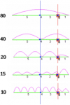
If you look at the current distribution along an OCFD its the same as a center fed with maximum current in the center on its fundamental freq, a current null in the center and two high current points either side at 2X fundamental and so on. Here is the current distribution posted for an "OCF Masters Antennas" 80m OCFD on multiple bands. Its basically the same as a center fed or an end fed antenna of the same length and the red line would be the tap point for the 4:1 balun.

1641679632990.png

I'm not so sure about a 1/2 wave dipole being resonate when it is cut off center by a balun. One element will be more or less in resonance and receive a signal but the other element will not and be more or less dead and creates a huge inbalance in a one core balun that creates that current mode issue. Hence the need for that two core guanella balun.

I see users claim that their VHF/UHF discone works just as good as their proper HF wire antenna, so it probably doesn't matter much what you do with your antenna at shortwave frequencies, as long as its big enough in size and you have a good match when you transmit.

/Ubbe
 

Ubbe

Member
Joined
Sep 8, 2006
Messages
9,039
Location
Stockholm, Sweden
If you look at the current distribution along an OCFD
At 80 meter the balun are at the 200 ohm point and needs that 4:1 balun. At 40 meter the balun will be at the 50 ohm point of the wave, using a 200 ohm balun. At 20 meter the balun are placed at the minimum wave at 2000 ohm using a 200 ohm balun. It's a terrible antenna design. But antenna placement and if it's sloping, inverted V or just an elevated dipol probably have much more impact than being of an OCFD design.

/Ubbe
 

prcguy

Member
Joined
Jun 30, 2006
Messages
15,360
Location
So Cal - Richardson, TX - Tewksbury, MA
All my OCFDs have a very good match on all bands including 20m so the balun could not be at the 2000ohm point, that would give a 10:1 match. Different companies use different tap points, I suggest you model one with a 19/81% tap point and see how it plays out.

I've probably tested and used more HF antennas than most people and the 133ft 80 through 10m OCFD from MyAntennas is the best I've used for a multiband wire antenna.

At 80 meter the balun are at the 200 ohm point and needs that 4:1 balun. At 40 meter the balun will be at the 50 ohm point of the wave, using a 200 ohm balun. At 20 meter the balun are placed at the minimum wave at 2000 ohm using a 200 ohm balun. It's a terrible antenna design. But antenna placement and if it's sloping, inverted V or just an elevated dipol probably have much more impact than being of an OCFD design.

/Ubbe
 
Status
Not open for further replies.
Top