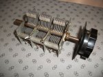
Okay I think I am ready to build AM loop antenna for MW

Status
Not open for further replies.

scan_madison

Member
Joined
Aug 18, 2012
Messages
115
Location
USA
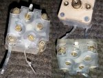
All the references I have read online, including FAQ on this site, talks about using lengths of wire and a good quality variable capacitor. I have finally obtained a plastic capacitor from my friend who mentioned it was pulled from AM/FM/SW radio. My question is whether this would work and how to go about soldering the contacts. It has four points. Plus, it is missing a knob. Is there a way to check it using a multi-meter? My goal is to make an antenna similar to Tecsun or Terk inductive loop antenna. Below is the collage of images.

collage.jpg

Another question: Can I simple get a fixed value capacitor, let's say, for 640 kHz single frequency reception? I'm sure there's a calculation that will tell how much pF capacitor I'd need. Thanks in advance.
 

ka3jjz

Wiki Admin Emeritus
Joined
Jul 22, 2002
Messages
25,706
Location
Bowie, Md.
What an interesting question - if no one answers (and I can't believe that would happen) there's actually a Facebook group that has a lot of folks doing homebrewing just as you are....


Mike
 

MDScanFan

Member
Joined
Jan 23, 2010
Messages
372
Location
USA
If you have a multimeter that measures capacitance then measure between various contacts as you adjust the variable capacitor. From that measurement it should become obvious which contacts are the ones you want as well as the range of values each variable capacitor provides.

Yes, you can use a fixed capacitor for a targeted frequency. The value needed will depend on the geometry (inductance) of your loop and the target frequency.

You can also use a fixed capacitor to augment the range provided by a variable capacitor, if needed. For example, you can switch it in for one part of a band and switch it from out for another part of the bandwidth.
 

wa8pyr

Retired and playing radio whenever I want.
Staff member
Lead Database Admin
Joined
Sep 22, 2002
Messages
7,285
Location
Ohio
All the references I have read online, including FAQ on this site, talks about using lengths of wire and a good quality variable capacitor. I have finally obtained a plastic capacitor from my friend who mentioned it was pulled from AM/FM/SW radio. My question is whether this would work and how to go about soldering the contacts. It has four points. Plus, it is missing a knob. Is there a way to check it using a multi-meter? My goal is to make an antenna similar to Tecsun or Terk inductive loop antenna. Below is the collage of images.

That's a polyvaricon capacitor. There are actually two sections to it; since it came out of a broadcast band radio it's possible that both sections are approximately 0-365 pF (picofarads) which is a common value for a BCB radio; it could also be 0-20pF + 0-365pF and so on. What you really need is the 0-365pF section, although the 0-20pF section would limit your tuning range if you really wanted to do that, but you would need to make sure the inductance of the loop is really close to what you actually need.

You can use a multimeter to determine capacitance if it has a capacitance meter function built in; otherwise you would need a capacitance meter add-on for your multimeter, or an actual capacitance meter.

There are ideas for knobs here:
Also check Mike's Electronic Parts, all kinds of neat stuff: Mike's Electronic Parts – Hard to find electronic parts

Another question: Can I simple get a fixed value capacitor, let's say, for 640 kHz single frequency reception? I'm sure there's a calculation that will tell how much pF capacitor I'd need. Thanks in advance.

You could do this, but I'd recommend going with the variable capacitor. Various things can cause the inductance of the loop antenna to vary including the size of the wire, the number of turns, the spacing of the turns and the diameter of the loop, even what's adjacent to the loop, so you would be much better off using the variable capacitor so you can tweak it as needed.

A lot of the fun of this is fiddling about with stuff to see what happens. Best bet is to build the loop following the instructions, and hook up one side of the capacitor to the feed loop; if it works you're all set and if not, try the other side of the capacitor. You could also try putting the sections of the capacitor in parallel or series to see how that affects things.
 

majoco

Stirrer
Joined
Dec 25, 2008
Messages
4,315
Location
New Zealand
Hi, sorry, but I disagree
it could also be 0-20pF + 0-365pF

If there's only two variable capacitors in there, the ones that move with the main spindle. then they are quite usefully the high values, one for the RF coil tuner and one for the oscillator tuner in a superhet radio - you were probably thinking of an AM/FM radio but that will have four variables.

If you can see through the sides of the 'box' then you'll hopefully see two sets of fixed 'vanes' that don't move when you turn the knob. One of the corner solder tags will be connected to one set of these vanes. Then as you turn the knob you'll see another set of vanes move and mesh with the fixed ones and another solder tag will connect to these moving vanes. Those two tags are the one that should go to your coil and you have another two for the other capacitor. The four 'screws' are small value variable capacitors used for alignment which you can ignore.

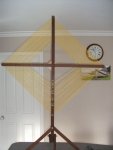
Unfortunately you picked the hardest capacitor to use, one like this is a lot easier but more expensive and rare these days. I made a big loop like this and a three section capacitor....

I wanted to tune down to the low frequencies for the aero beacons but couldn't tune the whole range.
 

Attachments

  • DSCF1100 sml.jpg
    DSCF1100 sml.jpg
    87.2 KB · Views: 16
  • loop for ARF.jpg
    loop for ARF.jpg
    51.3 KB · Views: 15

scan_madison

Member
Joined
Aug 18, 2012
Messages
115
Location
USA
Thanks for all responses. Since I don't have a LCR meter, I will just have to give it a try and see if it works.
 
Status
Not open for further replies.
Top