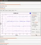
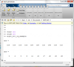
That is interesting looking; looks like the 4 possible symbol bit pairs. This is clearly out of the demodulation process and nothing else; i.e., before any data processing. Yes, that looks pretty solid. Again, was this a C4FM sgi\\ignal or QPSK? (I can't remember which is used for LSM, and what phase and all that.) And was this a strong signal that sounded good?? Just thinking aloud, if there were any errors biases in the demodulation, it might show up as the median values of these lines being shifted up or down, or a 'spread' of the samples around the lines.
And speaking of biases and such, a thought just struck me. Are these scanners designed primarily for plain old analog FM use? The reason I ask is the the actual demodulator for TDMA is quite different from the typical demodulator (discriminator) for FM. Most all radios today use what is called a quadrature detector to recover FM; it is a bit different from the older discriminators but works fine for FM and is easy and cheap to implement. All of the receiver IC's since the late 80's that I have seen use them.
For TDMA's QPSK demodulation, an IQ demodulator is used. There is a huge difference between an IQ detector and a quadrature detector. An IQ detector allows the amplitude variations in the received QPSK waveform to be part of the demodulation process. This is important as the narrow shape filtering applied to the transmitted QPSK signal puts amplitide variations on the signal that have to preserved in the detection process. (More below.)
A quadrature detector has a hard limiter before the final detection process that strips off all the amplitude variations. The only time it responds to amplitide variations is when the signal is weak, and then it has an undesired characteristic of squaring the amplitude variations; i.e, it is not linear when the RF/IF signal level falls below the hard limiter level. (That is why, when an analog FM receiver's signal gets weak, the noise popping is so much more severe than for an AM radio signal.)
I think you can recover C4FM fairly well from a quaradture detector, as C4FM has a constant amplitude (as I presently understand it). But receiving QPSK with a quadrature detector will be a compromise at best, and I would expect it to really fall apart in weak signal conditions. So, does anyone have a link to a schematic for one of these scanner receivers, so we can maybe see if it has a quadrature detector?
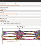
And if you want to see what a real IQ constellation looks like for a QPSK signal with all its important amplitude variations, and how it effects demodulation looks at this link and read on below:
http://www.aeroflex.com/ats/products/prodfiles/appnotes/548/lsm.pdf
In the bottom left corner on page 3, show what a real IQ (constellation) diagram looks like for QPSK; this is a clean QPSK signal BTW, not a weak, noisy one. The 8 sharp points on a constant diameter circle (unit circle) are the ideal phase-amplitude points. See all the lines inside of, and loops outside of, the unit circle on which the phase points lie? Those are the actual transitions of the instantaneous signal phase and amplitude between one QPSK point and the next. In ideal conditions, your symbol sampling of the signal take place precisely at the moment that the instantaneous signal crosses through one of those sharp phase points. And if you get a weak signal, the noise causes the instantaneous signal to 'miss' the ideal phase-amplitide point by some amount, and the result is that sharp points blur and get fuzzy and spread out, and you get detection errors if the instantaneous signal misses an ideal point by too much.
If you don't faithfully preserve the instantaneous phase-amplitide 'meanderings' in the QPSK signal in the detection process, then the instantaneous signal will consistently miss the ideal points, even with a good signal. A quadrature detector's limiter will strip off all the 'loops' of signal outside of the unit circle, and it will distort the 'crisscross' lines inside of the unit circle. So, no matter how you sample it, you will always have some detection errors as the instanteous signals will consistently miss the ideal points.
And, the above link is good to show the signal's shape filtering on the same page. (I called it a window filter in the last post, which is the wrong term.)
Well, that is one other thought on this topic, for what it may be worth; I hope the explanatoin is clear enough to follow. Again, if anyone has a link to the schematic for this scanner, I'll try to look at it and decipher the demodulator type. Regards, Mark B.
PS: And the paragrpah on "Why LSM is utilized" in this Aeroflex app note is mostly marketing bull-cr*p, especially the claim that the amplitide variation in QPSK help in-building penetration. I run a premier engineering biz in the distributed antenna system market (and spent extensive R&D time in all of this), and that is pure fiction! Where is the 'rolling in uproarious laughter' emoticon !?! (Sorry, but I tend to react to this fictional marketing junk, as it inevitably takes hold and people who know the truth gets looked at askance when they try to tell the truth.)