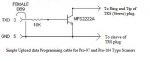
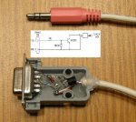
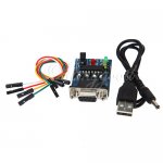
Programming Cable Pinout?

Status
Not open for further replies.

gmclam

Member
Premium Subscriber
Joined
Sep 15, 2006
Messages
6,391
Location
Fair Oaks, CA
Serial cable

As to adapting the original circuit you posted by separating the TX and RX, dosen't it have a 5 volt signal level on the scanner side? I would think it would not be useable for his Pro-163 either.
The circuit I posted does not have any voltage on the scanner side - it is open collector. That is, there is no "drive" signal from the circuit. That's why it works on such a boad selection of scanners.

Note that the difference between the PRO-163/PRO-164/PSR-300 and the PRO-97 in this regard is the PC/IF connector used. The PRO-97 uses a "mono" connector and the newer scanners use a "stereo" connector. Otherwise the radio models are quite similar and there's no other reason the circuit should not work.

I mentioned that one way is to bring out a separate wire from an unused power connector. I think that would be better than tapping a USB port for power.
Sounds scary to me. USB ports are designed to provide external power. But I'd rather not deal with it at all, unless I am building a USB type cable.

Yes an extra wire to connect is a bit awkward but would work ok for a situation where a programming cable is attached to one computer and left there.
So you're building a cable that you'll leave on one computer. I've got 2+ desktops here in use all the time and a laptop for on the road. Rather than tap into a computer for power it might as well use a separate wall wart.

there is a circuit that taps the RTS and DTR signals on the DB9 and uses a couple of capacitors and a TTL logic chip to provide 5 volt power to the MAX chip. I will post that if he is interested in doing it that way.
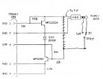
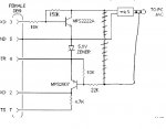
Gee, that reminds me I have such a device I designed for another customer. I'll have to look at it to see how easily it could be adapted to a scanner. But my device doesn't need the MAX232 either.

The description talks about a MAX232 chip but the picture shows an ADM3232 - I am not sure what is up with that and plan to email them to see what I actually would get.
It appears to me (without reading the part spec) that the part can work at either 3.3v or 5v by powering it from that voltage. So if you ignore 5v scanners and power it from 3.3v that would work. But now you need 3.3v - 5v from the PC is more available.
 

Evert

Member
Joined
Jul 29, 2008
Messages
332
Location
West River South Dakota
Sounds scary to me. USB ports are designed to provide external power. But I'd rather not deal with it at all, unless I am building a USB type cable.

I don’t see anything scary about taking power from the same 5-volt bus that USB ports get their power from. And USB ports are known to be weak in the amount of current you can draw from their 5-volt connector. (But the MAX chips don’t draw much current so using a USB port may be feasible.)

So you're building a cable that you'll leave on one computer. I've got 2+ desktops here in use all the time and a laptop for on the road. Rather than tap into a computer for power it might as well use a separate wall wart.

No, I just thought spokehedz might have only one computer.

I have four working XP desktops, three working XP laptops, one working VISTA laptop and four XP desktops that could be working if I could find my roundtuit. Also I have three Windows 98 laptops that have RS232 ports but no USB ports. There are at least four 80486 computers, which of course do not have USB ports. I think I even have an old 80286 laptop but last year I dumped my IBM Convertible and my Compaq “portable” suitcase size monstrosity.

Plus I am the volunteer computer room activity leader at my Senior Center. There we have five XP desktops, and one Vista desktop but I use only one of those for programming my scanners while I am there.

So if I do get a couple of the boards to tinker with I most likely will use a walwart for the power source.

It appears to me (without reading the part spec) that the part can work at either 3.3v or 5v by powering it from that voltage. So if you ignore 5v scanners and power it from 3.3v that would work. But now you need 3.3v - 5v from the PC is more available.

If it does need 3.3volts it would be simple to add a regulator chip to the circuit board.
 
Last edited:

Evert

Member
Joined
Jul 29, 2008
Messages
332
Location
West River South Dakota
powering MAX from RS232 port

Here is a version of getting power from the com port that I mentioned I had seen:

With a different voltage regulator it could provide most any voltage needed for other devices/projects.
 

Attachments

  • power from rs232 port.gif
    power from rs232 port.gif
    5.5 KB · Views: 4,667
Last edited:

gmclam

Member
Premium Subscriber
Joined
Sep 15, 2006
Messages
6,391
Location
Fair Oaks, CA
I don’t see anything scary about taking power from the same 5-volt bus that USB ports get their power from.
Yeah it is always better to get your power directly from those overhead power lines rather than through all those pesky breakers, fuses and other protective devices.

And USB ports are known to be weak in the amount of current you can draw from their 5-volt connector.
Yeah that 1 amp of current might not be enough to run the MAX232 and who knows what else.

No, I just thought spokehedz might have only one computer.
And NO one else will be interested in this. And those parties who are interested will have a computer which they will gladly 'hardwire' this thing to.

If it does need 3.3volts it would be simple to add a regulator chip to the circuit board.
And since you're picking parts that are in a junk box somewhere I doubt you'll be using a LDO (low drop-out) or efficient regulator. Be sure to put a big enough heat sink on it.
 

Evert

Member
Joined
Jul 29, 2008
Messages
332
Location
West River South Dakota
Yeah it is always better to get your power directly from those overhead power lines rather than through all those pesky breakers, fuses and other protective devices.

I always fuse any device (or the wire to it) I make that plugs into a computer’s power no matter from what point I tap it from – even if I were to tap a USB port for power. Same as I fuse any tap I make into the power bus or to a fused circuit of my cars.

Yeah that 1 amp of current might not be enough to run the MAX232 and who knows what else.

Didn’t you notice that I said “But the MAX chips don’t draw much current so using a USB port may be feasible”?.

A USB root hub may be good for 1000ma (or more if it supports more than two ports) but each port is good for 500ma at most. At least that is what all of my computers reported when I checked them. And not all computers are capable of providing that much power. There are a lot of laptops out there that have notably weak USB ports.

But enough of this – I don’t like to tap USB ports and you do, so lets just leave it that way.

And NO one else will be interested in this. And those parties who are interested will have a computer, which they will gladly 'hardwire' this thing to.

I don’t know if anyone will come along that will be both interested and willing to “hardwire this thing” but I think there could be some.

If no one is both interested and willing to do the hardwiring, then they can use one of the other methods I or you mentioned. If they are not willing do any of those then I guess they will just have to find another way or buy a programming cable.

And since you're picking parts that are in a junk box somewhere I doubt you'll be using a LDO (low drop-out) or efficient regulator. Be sure to put a big enough heat sink on it.

It was spokehedz who is adamant about using only parts from his junk box. I do not intend to so limit myself.
 

Evert

Member
Joined
Jul 29, 2008
Messages
332
Location
West River South Dakota
Adapt gmclam's cable for both type scanners

…..
One could just take the above cable and separate TX from RX …..

Other that trying to accommodate spokehedz’s desire to use a MAX chip I think that is one of the better ways to go. I think I may build one to have for use on my laptop computers that have a RS232 port and no USB port or a single port that I like to use my mouse on.

I think I have all the parts in my junk box including a DB9 shell that probably has room enough to put the components inside.

I would put a small SPDT switch on it to connect the lead coming from the 22k resistor to the tip of a TRS plug when using my Pro-97 and connect it to the Ring when I use my Pro-164. The collector of the NPN transistor will remain connected to the Tip of the TRS plug at all times.

If a person wanted to just upload data to their scanner I think one could use just the upper, open collector, portion of the circuit with the collector connected to the tip of a TRS plug and leave the Ring float. That should work for both type scanners without a switch and would be a very simple circuit that requires only one resistor (two if the 150k resistor’s function was wanted) and one npn transistor.

I am pretty sure that WIN97 will send the data without checking to see what is attached and thus would not need a response from the scanner. I have seen a full transfer indicated even when no scanner was connected to my RS 20-047 cable.
 
Last edited:

gmclam

Member
Premium Subscriber
Joined
Sep 15, 2006
Messages
6,391
Location
Fair Oaks, CA
Evert, you probably don't need the switch. PRO-97s work with both the stereo and mono cable ends (for example the 20-047 USB version cable has a stereo end on it).

As far as "readback" is concerned, yes there is an option in WIN97.

As far as USB goes, you can purchase a USB to COM cable for about $5. I had to use that to program a Uniden scanner. The scanner came with only a COM version cable, and the software would not run on my older PC which has COM ports. So I used the USB to COM converter no problems.

The only issue I can see is that the software you're using must support the COM# that is assigned to the cable.

I already have one of each type of cable (COM & USB versions) but I don't like the fact I can not program my PSR-300 from my NT machine (NT does not directly support USB ports). So my desire is to build this COM version cable with a stereo plug. I think the MAX232 is overkill and a relative power hog. If someone has a MAX232 in their junk box, they should also have a couple of suitable transistors.
 

Evert

Member
Joined
Jul 29, 2008
Messages
332
Location
West River South Dakota
Evert, you probably don't need the switch. PRO-97s work with both the stereo and mono cable ends (for example the 20-047 USB version cable has a stereo end on it).

Yes I know that the Pro-97 will work with both stereo and mono plugs that is why on my suggested adaptation of your circuit I mentioned using a stereo plug (instead of the mono plug of the original circuit). (Sorry, I guess I may have not made it clear that only a stereo plug was to be used.)

The switch is so the signal coming from the scanner will taken from the tip of the stereo plug when using a Pro-97 type scanner and from the Ring of the stereo plug when coming from a Pro-164 type scanner.

That way all you have to do to change scanner types is to flip the switch.

As far as USB goes, you can purchase a USB to COM cable for about $5.

I have a USB to COM cable that I use to connect my older Garmin Etrex and Etrex Legend to my newer computers.

But I was not seeking a way to connect to a USB port (I have a RS 20-047).

The laptop computer that I want the RS232 cable for has only one USB port and I prefer to using my mouse on that. (It is getting hard to find PS2 mouse and I have several USB mice.)

As far as "readback" is concerned, yes there is an option in WIN97.

Thanks, after you posted that I went to the Serial Configuration box and see where the readback tests can be disabled.

I am at the Senior Center right now but when I get home I am going to quick make the one resistor, one npn version and see it I can upload data with it. Now that I know I can disable read back I can not think of any reason that simple circuit will not work.

I think the MAX232 is overkill and a relative power hog. If someone has a MAX232 in their junk box, they should also have a couple of suitable transistors.

I agree fully with that ;)
 
Last edited:

gmclam

Member
Premium Subscriber
Joined
Sep 15, 2006
Messages
6,391
Location
Fair Oaks, CA
The switch is so the signal coming from the scanner will taken from the tip of the stereo plug when using a Pro-97 type scanner and from the Ring of the stereo plug when coming from a Pro-164 type scanner.
I guess that's better than using an adapter. Although I'm not sure why the 20-047 works on a PRO-97 without such a switch (and has readback).

The laptop computer that I want the RS232 cable for has only one USB port and I prefer to using my mouse on that. (It is getting hard to find PS2 mouse and I have several USB mice.)
You can also get a USB expander or hub that will allow multiple USB devices on a single physical connection.
 

Evert

Member
Joined
Jul 29, 2008
Messages
332
Location
West River South Dakota
I guess that's better than using an adapter. Although I'm not sure why the 20-047 works on a PRO-97 without such a switch (and has readback).

I think the 20-047 does some electronic switching. You can use readback with this mod. It is the single resistor- single npn mod that I wanted to turn off the readback for.

But using a stereo jack to mono adapter when hooking to the Pro-97 will work as well, if you want to carry yet another piece.

You can also get a USB expander or hub that will allow multiple USB devices on a single physical connection.

Yes I have an expander hub too, but that would be another piece to carry along. Besides I like to tinker and want to make this cable. :) Also it would be a backup in case I lost or damaged my 20-047.


Below is a sketch of the modifications. Of course some of the indicated connections are not the actual solder points.
 

Attachments

  • modified cable -1.jpg
    modified cable -1.jpg
    53.7 KB · Views: 4,774
Last edited:

Evert

Member
Joined
Jul 29, 2008
Messages
332
Location
West River South Dakota
no switch version

Below is a version of the mod without a switch. For Pro-97 type use a real stereo jack to mono plug adaper - the RS 20-047 pigtail will not work on this.

For Pro-164 type use without adapter.
 

Attachments

  • modified cable -2.jpg
    modified cable -2.jpg
    52.3 KB · Views: 4,453
Last edited:

Evert

Member
Joined
Jul 29, 2008
Messages
332
Location
West River South Dakota
Pinouts Revisited

I built the one-resistor-one-transistor simple TXD only cable and made an interesting discovery.

At first I had the signal (i.e. the npn transistor's collector) connected to the tip of a TRS plug and figured it would work that way for both the Pro-97 type and the Pro-164 type scanners.

It worked ok on my Pro-97 but would not work with my Pro-164. So I tried hooking the signal to the ring section of the plug and that made it work for the Pro-164.

Then I hooked the signal to both the ring and the tip at the same time and found that configuration works for both the scanners.

This makes for a very simple Q&D cable that can be used upload data to both type scanners with no additional adapters required (provided it is used with a computer that has an RS232 com port.)

Or if someone already has a USB to RS232 converter cable this simple programming cable should be useable with that for computers with no RS232 com port.

But now I see that the connections shown on the sketches I showed in posts 30 and 31 will not work and need to be rearranged so that the signal coming from computer’s TXD via the circuit goes to the ring of the TRS plug.

The signal coming from the computer’s RXD via the circuit should be hooked to the tip. I believe that would make the cable work for Pro-164 types, and that putting on a true stereo-to-mono adapter would make it work for the Pro-97 type scanners.

Sketch of the simple upload-only programming cable below:

…
 

Attachments

  • SRSTPC.jpg
    SRSTPC.jpg
    12.3 KB · Views: 3,305
Last edited:

Evert

Member
Joined
Jul 29, 2008
Messages
332
Location
West River South Dakota
Added a diode

I added a diode to the single resistor, single transistor circuit after seeing it on some other sites. Apparently its purpose is to present the 10k resistor as a finite load while the TXD signal is negative.

I don’t know if it is really necessary but I added it to the one I made since I have lots of the 1N4148 diodes in my junk box.

This cable works to upload data on my Pro-97, Pro-164, and Pro-160.
 

Attachments

  • SRSTSD programming cable.jpg
    SRSTSD programming cable.jpg
    102.1 KB · Views: 6,062
Last edited:

gmclam

Member
Premium Subscriber
Joined
Sep 15, 2006
Messages
6,391
Location
Fair Oaks, CA
I added a diode to the single resistor, single transistor circuit after seeing it on some other sites. Apparently its purpose is to present the 10k resistor as a finite load while the TXD signal is negative.
It also keeps from reverse biasing the transistor. Keep in mind the TX signal goes from "-12" to "+12" volts, not from ground.

Nice picture, thanks.[/QUOTE]
 

Evert

Member
Joined
Jul 29, 2008
Messages
332
Location
West River South Dakota
You are welcome.

I have also seen similar circuits with a 10k resistor where the diode is in the circuit I posted.

What are your thoughts about whether either of those would be necessary in the application being used here?

I knew that the RS232 specs call for the signal swing from –12 volts to + 12 volts that is why I said “while the TXD signal is negative”. But isn’t that with respect to circuit ground? It was my understanding that all the voltages in the RS232 specs are measured with respect to circuit ground. Or did I misunderstand what you mean by “not from ground”.
 
Last edited:

pro92b

Mutated Member
Premium Subscriber
Joined
Jun 27, 2002
Messages
1,943
The resistor is needed to set the transistor base current when the input is positive. When the input is negative it can drive the transistor base-emitter junction into reverse avalanche breakdown. That occurs around -7 volts. The resistor will limit the reverse current to a few tenths of a milliamp and considering the intermittent usage of the cable, there is not much chance of damaging the transistor if there is no diode. A MAX232 will put out +/-10volts at best and many computers output +/-8 volts or so. The diode clamps the negative voltage to -0.7 volts which prevents any chance of emitter to base breakdown. Again in this application it probably doesn't matter much if the diode is absent.
 

gmclam

Member
Premium Subscriber
Joined
Sep 15, 2006
Messages
6,391
Location
Fair Oaks, CA
What are your thoughts about whether either of those would be necessary in the application being used here?
If all you want is a cable which can do the downloads, then the extra components are not needed. In the original schematic they added the 150K resistor to handle the condition of when one end of the cable is plugged in and the other not. You're also going to get different measurements depending on the type of serial port you connect to. There's never an end to adding "protective" components for all kind of conditions.

I knew that the RS232 specs call for the signal swing from –12 volts to + 12 volts that is why I said “while the TXD signal is negative”.
I'd have to check the spec for RS-232, but I think the actual requirement is somewhere around +/-7 volts. Original ports that used 1488s & 1489s would swing +/-12 (depending on applied supply voltage) and ports like which are driven by a MAX232 are slightly less than +/-10 volts (2 x 5v). This is why I put my "+12" in quotes.

But isn’t that with respect to circuit ground? It was my understanding that all the voltages in the RS232 specs are measured with respect to circuit ground. Or did I misunderstand what you mean by “not from ground”.
You were clear to me, but I am not sure how others reading this will interpret. Most people don't think about voltages going below ground. I just wanted to point out that the RS-232 signals from the computer (in this case) do swing above and below ground. So when TX is negative, it is reverse biasing the transistor. Current is limited by the 10K resistor. I'd have to look at the spec on the transistor, but then again it wasn't an issue in the original design (apparently).
 

Evert

Member
Joined
Jul 29, 2008
Messages
332
Location
West River South Dakota
Thanks for the responses Pro92b and gmclam. It is being fun for me to knock off some of the rust on my transistor knowledge. It was never all that deep anyway even though my brother gave me some technical papers on them when he was an EE student at Purdue in 1959. He handed them to me and told me to study them because “this will be the electronics of the future”. This to me who was a ME student at Ohio College of Applied Science. :) But I have always liked electronics and have dabbled with it for a long time.

I worked quite a bit with computer external modems while working for BLM in Butte Montana in the 90’s and knew quite a bit about them but that knowledge is pretty rusty too.

I see that using the diode would limit the emitter-base reverse bias to around –1 volt and using a 10k resistor instead of the diode would form a divider and limit the reverse bias to one half the TXD mark (negative) signal level.

What is difficult to know is how negative that mark signal will be. RS232 specs say that transmitted space signals can be as low as +5 volts and high as +15 volts. The mark can be –5 volts to -15 volts. I guess designers of equipment that were going to need long cables between devices would use the higher absolute value of these digits. Equipment to be coupled at shorter distances could use smaller numbers.

I suppose since personal computers originally used the “RS232” ports mainly for external modems that usually had very short cables the actual signal level could be on the lower end. Also I have read that computer RS232 ports do not necessarily comply fully to the RS232 standards. Pro92b said that "many use +/- 8 but to me "many" is not very assuring.

It may be safe to assume that the most negative that computer TXD mark signals would get is –12 volts and half that would be –6 volts.

If so, the 10k resistor I mentioned being placed where the diode is would prevent exceeding the –7 volt reverse bias breakdown voltage pro92b mentioned. But that is a narrow margin based on an assumption.

Just for the fun of it, I may measure the mark and space levels on several of my computers just to see what they are using.

But bottom line, is that I am going to use the diode even though Pro62b says it probably isn’t necessary. And using a diode instead of a resistor does away with the guesswork of how much the reverse bias voltage will be.

By not exceeding the reverse bias breakdown voltage I know my cheapo old Archer Pak pseudo PN2222 transistors will have a better chance of surviving. (I plan to build several of these to give to some of my friends.)

Gmclam, during my career I was often accused of designing equipment “hell for stout” and then beefing it up a bit. Why should I quit now :)
 
Last edited:

Encrypter

Member
Joined
Apr 12, 2012
Messages
6
Location
Hartford, CT
GRE PSR-300 (PRO-164) Data Cable home made diy

I have the GRE PSR-300 scanner. This should also work for the PSR-400 PRO-163 & PRO-164 possibly others too. I made the diy cable without using USB. I ordered a MAX232 5v supply RS-232 serial chip, actually got it assembled already on a circuit board with a db9 connector for the pc and a cord to get 5v power from a USB port. Get your power from any 5v source. I put my DMM on the power and the whole thing draws 16ma idle, 20ma durring a transfer, thats virtually nothing for current. I got the chip/board from ebay for $5. I cut the stereo 1/8th plug and cord from old headphones.

Connect the Tip & Ring together and then connect that to Tx & Rx together (loopback with a tap basically, and short left/right together). It wouldnt work with the software until I connected Tx Rx Tip Ring all together so that the software could see looping back what it sent out to the scanner. I tested with Win97 and ARC300. This was very easy and cost me only $5, lot cheaper than usb cable. Next I will try it on PSR-310.

MAX232EPE PSR-300 1/8th stereo
Tx-----+----------+-----Tip
| |
Rx-----+ +-----Ring
 

Attachments

  • MAX232-board.jpg
    MAX232-board.jpg
    57.2 KB · Views: 2,678
Status
Not open for further replies.
Top