Radio Shack Pro-2025 I need a resistor value

Status
Not open for further replies.

MrBruce

Member
Premium Subscriber
Joined
Jun 2, 2013
Messages
11
Location
Norwich, Connecticut. USA
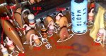
I have a Uniden Bearcat BC 560XLT scanner. The circuit board is the same as the one that is in the Patrolman 2025 scanner. I had a resister burn up and the scanner lost it's ability to receive any of the frequency bands it is designed to receive.

I do not know what value the resister was, so I replaced it with a common resister value of 100 Ohms. The bands still fail to receive any of the bands. I have used a signal generator and it appears that one of the IF stages is still operative, however I am sure the mixers are out of commission.

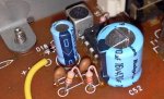
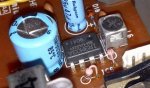
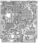
I have a schematic diagram of the scanner, the problem I am faced with is that Uniden did not mark the printed circuit board for the resistor part numbers. There is simply a marking for the resistors but no part numbers such as R1 or R15. I have tried unsuccessfully to find a printed circuit board map, so I can at least identify which resistor it is. I do know the resistor is in the power circuitry which includes the on-off switch and IC6 which is the IR3M03A chip.

The resistor is located right next to the D5 which is a diode.

What value in Ohms is this resister? If anything, please post what the color bands are on this resistor.

Thanks in advance.

Bruce.
 

RickS31

Member
Joined
Jun 8, 2010
Messages
515
Location
Sunrise FL
As a long term (30+ years) electronics tech and engineer, I can almost assure you that resistors almost never fail on their own, least of all "burn up". Burn ups usually are caused by failure of another component, typically a solid state one, that causes excess current to flow through the resistor.

This means even if you find the correct value and replace it your unit will still not work. Good luck with it though. Maybe you did have the .01% resistor failure situation.
 

KC4RAF

Member
Joined
Sep 30, 2006
Messages
1,579
Location
Davenport,Fl.- home to me and the gators and the s
Just as Rick posted, the resistor

more than likely failed due to another part. Some times a cap will short out causing high amperage to run through the resistor. Or a transistor or maybe a diode.
Have you tried Sam's Photofact site for that scanner?
Do you have a resistor setup board that you can switch in and out various resistor values? If so, you can place it in circuit and try different values till one comes up and allow operation to start.
Hope you get it going, sorry can't be of more help.
 

pro92b

Mutated Member
Premium Subscriber
Joined
Jun 27, 2002
Messages
1,969
D5 is near IC1, not IC6. Board diagram below.
 

Attachments

  • PRO202503.jpg
    PRO202503.jpg
    125.1 KB · Views: 1,199

SpectreOZ

Member
Joined
Mar 31, 2013
Messages
185
Location
Mildura, Australia
A close up of the D5 *diode (vicinity area) for the 2025 can be seen at the discriminator tap guide page HERE ;)


I'll pull the 2025 out of storage for you tomorrow and post better close ups (I just don't wish to wake up the house ferreting through cupboards tonight) :D
 
Last edited:

RickS31

Member
Joined
Jun 8, 2010
Messages
515
Location
Sunrise FL
I continue to be totally impressed by the folks on here including their resources available to the community as well as their knowledge. Great place to have available to you.
 

SpectreOZ

Member
Joined
Mar 31, 2013
Messages
185
Location
Mildura, Australia
I should mention the Radio Shack support pages list much detail regarding their current/former products, in fact a component list (including values) can be seen HERE for the Pro-2025 :D
 

Attachments

  • pro2025_resistors.JPG
    pro2025_resistors.JPG
    57.1 KB · Views: 708
  • rpo2025_resistors2.jpg
    rpo2025_resistors2.jpg
    60.7 KB · Views: 795
  • rpo2025_resistors3.JPG
    rpo2025_resistors3.JPG
    57.4 KB · Views: 769
Last edited:

MrBruce

Member
Premium Subscriber
Joined
Jun 2, 2013
Messages
11
Location
Norwich, Connecticut. USA
First off, Thank you all for posting all those pictures and links.

Now that I can see a visual layout, I realize how different the layout of the two circuit boards are.

First I have checked all of the diodes using an Ohms setting on my analog meter and checked the diode with the probes one way, then switched, one way was zero reading while the other was 10 Ohms. So the Diodes all checked out fine. Also the L7808CV Regulator checked out okay.

The circuits look similar, however the circuit board map in post # 4 looks like the parts were re-orientated around the board. My board has TJE 018HB and PH-164AC 1/4 printed on it.

Seems Uniden made some changes to the circuit board layout between the BC 560XLT and the Pro2025. I tried using Google for a SAMS manual, No go, at finding that.

I am not sure what happened and that SHARP IR3M03A IC is hard to find data on or even an available chip replacement if it is bad.

I could post a picture of this board if it would help.

Bruce.
Bruce.
 
Status
Not open for further replies.
Top