SDS100/SDS200: SDS100 Internal GPS Mod

Forts

Mentor
Database Admin
Joined
Dec 19, 2002
Messages
7,013
Reaction score
1,309
Location
Ontario, Canada
Hi all,

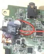
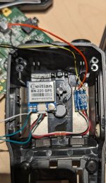
I did the internal GPS mod to my radio over the weekend and it's working great. The one issue I've discovered is that the GPS module does not power down with the radio. I'm currently using a point on the top left of the display board labelled VCC5 (see attached picture.... not my pic, just for reference as it's the only one I could find). Does anyone have an alternate switched source they could recommend? Otherwise I might just power the module from the USB port so it only powers up if the scanner is plugged in.
 

Attachments

  • SDS.jpg
    SDS.jpg
    105.1 KB · Views: 137

Aviator747

Member
Joined
Jun 14, 2006
Messages
170
Reaction score
132
Location
Cornwall, ON
What gps module did you use? I am getting a new to me SDS100, it's in the mail and I am exploring doing this. Yes, I can micro solder. Sorry, I have no current answer to finding a switched vcc.
 

Forts

Mentor
Database Admin
Joined
Dec 19, 2002
Messages
7,013
Reaction score
1,309
Location
Ontario, Canada
I used this module...
Geekstory BN-220 Dual GPS Glonass Module Navigation TTL Level 9600bps + GPS Passive Antenna for Arduino Raspberry Pi Pixhawk F3 CC3D Betaflight F4 Flight Control

Paired with one of these..
10Pcs Mini RS232 to TTL Converter Module Board Adapter MAX3232 120kbps 3-5V RS232 Serial Port Conversion Module, for Arduino MAX3232 Adapter Module Board

It's a little slow to get it's initial lock (usually 3-5 minutes) but works great after that. As for the power issue I ended up installing a little micro slider switch in beside the USB ports to manually control the GPS power. Acceptable solution for me.
 

Attachments

  • PXL_20240527_004626690.jpg
    PXL_20240527_004626690.jpg
    86.4 KB · Views: 117

Mojomanny

Member
Premium Subscriber
Joined
Nov 20, 2013
Messages
35
Reaction score
3
A little late to the party but I found this in a thread from Jon Wienke, hopefully it help

Just for clarification, the FET switching the GPS power is a P-channel BSS84. The resistor, capacitor, and diode network turn the power on when a ground or negative voltage is detected (like a RS232 data output), but keeps the power on even if the output is sending data.

The FET in the SDS100 cable is a N-channel BSS138. It senses a positive voltage from USB pin 3 (DATA+) and grounds the RS232 input line to turn the GPS on when the USB port is active. The 10MΩ bleeder resistor ensures the GPS shuts off if the cable is unplugged.
 
Top