Shack Grounding

KQ4RBK

Member
Joined
Apr 26, 2024
Messages
5
Location
Fort White, FL
Hi all,
New ham here. Trying to get my HF station set up and have a grounding question. I have tried to research things as much as I can but am stuck on the shack/RF grounding.

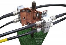
My shack is located in my office on one side of the house. Antenna is a dipole located off of the other side of the house. The coax from the dipole goes down to a lightning arrestor/surge protector mounted to an 8' ground rod right outside the house. It is along the same wall as the main utility panel, so I have the antenna ground rod bonded to the main house ground rod about 12' away. From there the coax goes about 50' through the exterior wall, up into the attic, across the house, and back down through the wall into my office shack.

Now I am trying to figure out how to ground the equipment in the shack. I have mounted a piece of 1/2" copper pipe to the back of my desk, and am going to connect all equipment chassis grounds to it using 1/2" copper braid. My question is, how do I now ground the copper pipe? My options as I see them are:

1. Drill a hole through the exterior wall of my office, and put another ground rod right outside to connect the copper pipe to. However, it would be very difficult to bond this back to the utility ground as it is on the opposite side of the house, and would have to cross a concrete driveway. My understanding is that code would require it to be bonded, but I don't know how to make that happen without many more ground rods and copper wire in between along with demoing the driveway...

2. Somehow (?) connect it to a ground wire inside of one of the electrical outlets in the office. This would connect it back to the house circuit breaker panel which is then tied back to the house ground. But everything I have read says you want "short, thick, or braided cable" to the ground rod. This connection would be to the 12awg (?) romex ground wire that would be neither short, thick or braided.

3. Run an additional ~50' wire or braid back up through the attic alongside the coax that ties back to the antenna ground on the other side of the house. Neither short, nor cheap.

4. Connect the equipment to the copper pipe as planned and then don't connect that to ground.

5. Do nothing and don't worry about it.

None of these options really seem ideal. Am I missing something?

Thanks!
KQ4RBK
 

K4EET

Chaplain
Premium Subscriber
Joined
Feb 18, 2015
Messages
2,347
Location
Severn, Maryland, USA
Hi @KQ4RBK,

Welcome to Radio Reference! You’ve come to the right place for answers.

Sounds like you have a good handle on grounding. You’ve probably done more than a lot of hams with respect to grounding the antenna but what you’ve done so far is very good.

You are in Florida where you can get some ferocious thunder and lightning ⛈️ storms. So grounding becomes very important for safety.

The number 1 solution that you mentioned above for inside equipment grounding is the preferred method if you tie the outside ground to your house ground. That being said, grounding the equipment to an outside ground rod is better than nothing. Just keep in mind that you will most likely have a potential difference between the antenna shield and the radio ground. Using 1/2 inch copper pipe and 1/2 inch braid is what I do on the inside.

Others will probably chime in and make comments giving you some other ideas. But you are on the right track for overall safety.

Let’s see what others have to say.

73, Dave K4EET
 

KQ4RBK

Member
Joined
Apr 26, 2024
Messages
5
Location
Fort White, FL
Hi Dave,

Thanks for the response. Yes, Florida lightning is a concern especially heading into storm season.

I agree, I'm guessing choice #1 is the textbook "correct" answer. I'm mostly trying to determine if the juice is worth the squeeze and how others have done it. It will probably be ~$300 worth of copper wire, rods, and clamps to get it bonded back to the utility ground. Not to mention a day's work and I still have to deal with the driveway problem. But I tend to be a buy once, cry once/do-it-right-the-first-time type of person, so if that's the consensus, that's what I'll do. My understanding is that our sandy soil is not the best for grounding either, so having a few extra rods in place around the perimeter of the house doesn't seem like a bad plan as far as lightning goes.

73
Daniel
KQ4RBK
 

KQ4RBK

Member
Joined
Apr 26, 2024
Messages
5
Location
Fort White, FL
Thanks, I think :) I'm trying to wade through it. I assume you are the author? You obviously have a lot of knowledge and experience but for someone that doesn't have a strong background in this stuff that is like drinking from a fire hose.

The part in section 6 and 8.1 about isolating the AC and DC power systems by removing the bonding jumper inside the DC power supply is interesting and makes sense. I will have to test mine to see if the DC negative is bonded to the chassis.

I think I understand most of section 7 regarding the EGP, breaking the ground loop, and avoiding the daisy chain.

I start getting a little fuzzy around section 8.2. You are the first person I've heard to suggest running a dedicated AC branch for the shack. I see how it could be nice to have an independent branch, but running it outside the house is logistically going to be difficult for me for a number of reasons.

I understand why a SPG is much better than a MPG as far as lightning protection (Fig 8). The issue I'm up against (I think) is the physical distance from that SPG to the shack. The point that the coax enters the house is not anywhere close to the shack, but it is close to the utility entrance. Aside from totally relocating the shack or the antenna, the only way I see to maintain a SPG is to run a conductor of some type from the station ground bar ~50' back through the attic to where the coax comes in. It seems like maybe you are depicting a similar situation in 8.2.3 Option 3. In Fig 6C, it seems like you are saying I should just run 50' of insulated, stranded 6awg back to the SPG?

Thank you,
KQ4RBK
 

KF5LJW

Banned
Banned
Joined
May 15, 2021
Messages
39
RBK sounds like you get the jest of it; good job. Let me see if I can bring this together and connect the dots. Once you see the big picture, you will understand nothing is complicated. I have a link to Mike Holt's NEC code forum, which I moderate on. Mike has a good White Paper on NEC article 810, which covers CB and Amateur radio antenna requirements. The pictures will tell you what to do and what I am about to say to you.

Single Point ground starts at your AC electrical service entrance. The AC service is grounded to what the NEC calls the Ground Electrode Conductor. It is the #4 AWG copper wire going straight down to dirt. Call it your AC Service ground.

Install a NEC-required intersystem bonding system device. That is code talk for a busbar, entry panel, hatch plate, ground window, or whatever you want to call it, a copper busbar large enough to terminate all the required connections. Bond the busbar to the AC Service Ground with a #6 AWG conductor.

Route all coaxes from the antennas directly to the ground bar you just made for your AC Service Entrance. Buy an antenna discharge unit (ADU) for each coax for surface mounting on a busbar. They have ¼-inch threaded studs to bolt them onto the busbar. Terminate the coaxes to the ADUs, then run inside the shack. You can run them outside the house under the eaves to the shack.

If you want or need a Station Ground, terminate a #6 AWG copper to the busbar and run it to the shack tightly coupled to the coaxes. In other words, they are zip-tied to the coax, forming a cable. Once inside the shack, terminate the Station Ground wire to a Busbar to allow you to make multiple connections. Be careful what you connect. For example, do not bond your DC power supply or anything with a three-wire power cord. All the AC equipment is properly bonded via its power cord. Your Station Ground is your DC Ground intended to ground your 12-volt DC toys. Run a dedicated #14 AWG ground wire from your station ground to your DC toys. That is what the ground stud on the radio equipment is there for.

See how easy that is? To enhance the lightning protection system, by all means, tap into the AC Service Ground and expand the Ground Electrode System. Run a 6 AWG solid bare tinned copper wire (buried radial) away from the house for at least 16 feet and pound an 8-foot rod in the dirt. If the wallet and back permit, run another 16 feet and pound another rod. That will direct a strike away from the house.

If you follow the advice above for your AC circuit, it will be no problem. You are not in a loop anymore. Your AC equipment and Station grounds originate from the same point; you have an SPG system. You will still want at least one dedicated 120-volt quad outlet. If you have a linear, you will need a dedicated 240-volt 15-amp receptacle. Run it conventionally.

To sum it up, run your coaxes to your AC service entrance. Bond a busbar to the AC service ground. Bond your coaxes to the busbar and run them inside with a station ground wire to your station ground bus. Whatever you do, DO NOT pound a rod outside the shack and bring a ground wire inside.

OK, now take a look at Mike Holt's document, and you should see it all come together. Good luck. Article 810 Guide
 

KQ4RBK

Member
Joined
Apr 26, 2024
Messages
5
Location
Fort White, FL
KF5LJW,

Thank you. I think that pulls everything together. I believe I'm more or less doing what you are suggesting already. It sounds like basically you are describing option 3 from my original post. I'm using one of the DX Engineering grounding rod plates for the antenna ground. It is bolted directly to an 8' ground rod and has an ADU bolted to it. Something like this:

dxe-ucgc-z_ur_xl.jpg

I assume this would function as what you are calling the "ground busbar" above. This ground rod is about 14' from the AC service ground rod and I bonded them together with bare 6awg copper.

I plan to bond all the DC equipment in the shack to a ground bar (1/2" copper pipe mounted under the desk). The piece I was missing was the 6awg wire running from the shack ground bar back to the outside ground. My confusion has always been that everything I read said that the ground connections should be short and direct. Running it in parallel with the coax 50' back through the attic didn't seem that short and direct, but that seems to be the best option.

A couple of follow up questions-- Why should the ground wire be tightly coupled/zip tied to the coax?

Also, you say to use 14awg wire from the station ground to the DC toys. I have heard many people say that this should be something like flat strap or copper braid because it has much lower impedance at RF frequencies. Is this not necessary in your experience?

I will take some time to ponder Mike Holt's document this weekend.

Thanks again for the knowledge.
 

KF5LJW

Banned
Banned
Joined
May 15, 2021
Messages
39
ou say to use 14awg wire from the station ground to the DC toys. I have heard many people say that this should be something like flat strap or copper braid because it has much lower impedance at RF frequencies. Is this not necessary in your experience?
Ham foolery. The station ground is a DC safety ground. Any ground wire is a Single Wire Circuit. It does not have an equal and opposite circuit conductor to cancel out the mutual inductance. Let's say we pounded a ground rod outside the shack and used a 10-foot-long 1/4-inch braid (equivalent to 6 AWG) into the shack station ground bus. What is the impedance of the conductor at 1 MHz and 10 MHz? If you consult the IEEE Emerald Book (the bible for high-performance grounding), we find the impedance at 26 and 260 Ohms, respectively. If we change the conductor to 6 AWG, it will produce roughly the same impedance. Up the 1-inch strap or 4/0 conductor as big as your wrist does not change the impedance significantly.

Now, let's add insult to injury. A ground rod is inductively coupled to the earth. Drive a single rod, measure the impedance at 10 MHz, and the impedance is in the Kilo-ohm range. Let's say you have excellent dirt. You drive your rods and see a 1000-ohm impedance. You connect your 10-foot ling copper strap in series with its 260 Ohms at 10 MHz, and your ground impedance is 1260 Ohms. Completely worthless. You could not push RF through your station ground wire if you had to. You would not want any RF current on your ground wires, so quit trying to force current on them. In fact, you may want to take a T240-31 core and wind as many wraps as you can with the 6 AWG wire just before you terminate to the station ground bar. If you experience RFI, that is the first thing to do. I have two choices on my station ground wire. One on both ends of my station ground wire. 14 AWG insulated wire is more than adequate. Other folks who wear belts and a suspender with a large battery system may use 12 AWG wires.

What confuses you is that most hams, the so-called Elmers, are stuck with the electrical systems of the 1960s. Around the mid-70s, the electrical codes changed drastically with respect to grounding. Walk into any old house, and you see the two-wire receptacles with no GROUND to be found. We were idiots back then. We used the neutral conductor as both a circuit conductor and ground. That made for a very noisy and dangerous world. Lots of folks were injured and killed. Hams made their own ground, which was also very dangerous. Ask some old fossils about connecting their TVs to the antenna and get shocked. Or Mom in the laundry room was shocked when she touched the washer and dryer. In the mid-'70s, the encodes changed with 3-wire with the ground. Hams never got the memo or noticed the changes. Modern homes use single-point ground. If you have current on your grounds, you have a serious problem on your hands.

Q. What do you call unwanted voltages and currents on ground wires?
A. NOISE
 

KQ4RBK

Member
Joined
Apr 26, 2024
Messages
5
Location
Fort White, FL
Excellent. Thank you for the education. I will probably have to reread all of this a couple more times to make sure it sinks in, but I think I'm on the right path. Much appreciated.
 
Top