UniScope Images for UniTrunker Troubles

Status
Not open for further replies.

William

Member
Joined
Mar 1, 2002
Messages
104
OK, all...

I'm still having trouble getting UniTrunker to run. I'm not sure if I'm getting a good signal to my computer.

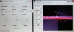
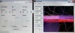
So...here's three screen shots of UniScope running.

To the left of UniScope is the Recording control panel. You can see that as I change the volume on the "mic" slider my scope image changes. So I beleive I am getting the signal to the computer. I just don't know if I'm getting a good signal to the computer. What's a good signal look like?

When I run UniTrunker I get a "** no signal **" message at the top of the screen. Right now my settings for UniTrunker are:

signal: normal
decoder: online
APCO P25: off
Signal input: via audio (WAVE)
Sample rate: 96000

I have tried to invert the signal and I still get the no signal messsage at the top of UniTrunker.

I'm sure I am doing or not doing something that is really simple to fix, but I have no clue what it is.

William
 

Attachments

  • scope1.jpg
    scope1.jpg
    62.8 KB · Views: 924
  • scope2.jpg
    scope2.jpg
    101.5 KB · Views: 932
  • scope3.jpg
    scope3.jpg
    73.8 KB · Views: 971

SCPD

QRT
Joined
Feb 24, 2001
Messages
0
Location
Virginia
Hi William;

Excellent pictures! Here's how I interpret these images.

Top - volume too low.
Middle - volume just right - but something else is wrong (more on that in a moment).
Bottom - volume is too high.

Here's what I think your problem is ...

Instead of a squarish wave for each pulse - you're getting what looks more like a sawtooth or shark's fin.

The causes may be one or more of the following:

(a) a capacitively coupled sound input.
(b) low input impedance on the computer's sound input - which is dragging your square pulses down.

Did you use a capacitor or resistor when you tapped your radio?

The way to deal with (a) is to replace the DC blocking capacitor (assuming you used one) a larger value OR replace the cap completely with a resistor.

To deal with (b) - the easiest thing to do is to install a small buffer pre-amp. The pre-amp will accept a weak high impedance signal and drive a low level but also low impedance input like your microphone or line input. The pre amp does not need any gain. It's really just there to isolate and provide an impedance match.

For pre-amps ... look for a "high-Z" microphone pre-amp from one of a number of electronic and hobby distributors. They can bought in kit form or pre-assembled.

If your tapped radio is a desktop or mobile unit - there's probably room inside to mount the circuit and have it draw power from the radio.

-rick
 

William

Member
Joined
Mar 1, 2002
Messages
104
Rick,

My radio tap was done at dataslicers.com. The literature sent back with the radio listed an optional 1k ohm resistor with a note saying that my tap did not need that since the data slicer sent with the tap included an internal capacitor.

From the radio to the laptop - which is a sony viao running xp, by the way - I have a simple wire. No pre-amps or anything.

I have not actually opened the radio since I got the tap last year. Should I open it to see if I have a capacitor?

Would a capacitor be the first step in getting a good signal? Then try a pre-amp? Or the other way around?

Finally - for the lack of a better technical term - it seems that my signal is not rising very high above the noise when I look at UniScope. For example in image #2 I can see the signal line, but it seems there is just a lot of junk rising half as high as the signal. Is that normal or is that part of what we're trying to get rid of?

Thanks for your help,

William
 

Go-24

Member
Joined
Mar 28, 2006
Messages
495
Location
Indiana
edited - I am an idiot! Upon further investigations today - I found that my microphone input was muted. GEEESH sorry for all the hastle on by part.
 
Last edited:

SCPD

QRT
Joined
Feb 24, 2001
Messages
0
Location
Virginia
William said:
Would a capacitor be the first step in getting a good signal? Then try a pre-amp? Or the other way around?
Your Sony almost certainly has an input capacitor so inserting another one would be redundant (might make the problem worse). I suggest adding a buffer amp (eg. a microphone pre-amp).

Finally - for the lack of a better technical term - it seems that my signal is not rising very high above the noise when I look at UniScope. For example in image #2 I can see the signal line, but it seems there is just a lot of junk rising half as high as the signal. Is that normal or is that part of what we're trying to get rid of?
I think your signal will be fine. Imagine a train of square pulses where the signal alternates between 0.0 and 1.0 volts. From left-to-right each pulse would appear as a rising edge followed by a flat peak that remains high for some brief interval and then drops back down. The corners can be slightly rounded. The rising and falling edges can have some "lean" to them. That's okay. However - the flat level part needs to stay level. What I see in your images is that the flat level portion of the square pulse is sinking towards zero volts well before the falling edge of the actual square pulse arrives.

A small buffer amp will help hold the level portion of the square pulses flat for the full width of the pulse (at least well enough for Motorola and EDACS signals - LTR is another story).
 

William

Member
Joined
Mar 1, 2002
Messages
104
Rick,

OK, so now where do I get a pre-amp?

I've read the other posts about pre-amps and saw that there are some places that sell fully assembled pre-amps but you noted that they were low-Z inputs. You said high-Z input would be better.

You also mentioned building a pre-amp that would draw power from the radio.

Any place you know of that I can get a pre-assembled high-Z input pre-amp that draws power from the radio?

As you might have guessed by now, I'm not a master electical engineer. Talk of Ohms, low-Z inputs, buffering, resistors, capacitors and the like starts to give me a headache after a while.

Thanks for all the help,

William
 

SCPD

QRT
Joined
Feb 24, 2001
Messages
0
Location
Virginia
William said:
OK, so now where do I get a pre-amp?
Good question - particularly for something pre-assembled. I think in your case you want something "plug and play". Providing power to the circuit would be the biggest hassle. You might end up with a small battery or separate wall-wart just to power the pre-amp.

Someone buying a kit will likely have the skills to wire the power leads to the appropriate places inside the radio or make a power plug "Y" adapter so the preamp takes power from the same wall-wart (AC power adapter) as the radio.

I don't have an answer for this one. The lo-Z input preamps would probably work (I have one that works fine) - but a hi-Z is preferred.

-rick
 

William

Member
Joined
Mar 1, 2002
Messages
104
Yes, plug and play would be prefered.

I think if I got a plug and play pre-amp, I could figure out how to get power to it.

My goal is to problem solve this one variable at a time. I'm affraid that if I build the circuit and install it and I still don't get a good signal, that I've just created more variables. Did I build it right? Did I intall it right? Is something else wrong?

If I buy a pre-built pre-amp and I still don't get a good signal, then all I have to worry about is my installation.

You see where I'm going with this? One step at a time and don't introduce any new problems?

William
 

William

Member
Joined
Mar 1, 2002
Messages
104
Rick,

Well, I've finally bought my pre-amp and got it running.

BUT, I'm still having problems.

I bought a Cana Kit amp that you posted a link to previously. I'm running the amp off a 9 volt battery.

I'm getting the same shark fin/saw tooth image with or without the pre-map when I compare the two in UniScope.

When I look at UniScope without the pre-amp it looks like the middle image in my previous post. When I insert the pre-amp I have to make adjustments on my computer volume, but the the image ultimately looks the same with the shark fin/saw tooth.

BTW...I have also downloaded the 32 version of UniTrunker just to see if the updated version works better with the signal I'm feeding to the computer.

Do you have any other ssuggestions?

Also, is there any chance someone could post a UniScope image of a good waveform so I know what I'm looking to replicate?

Thanks in advance.

William
 

William

Member
Joined
Mar 1, 2002
Messages
104
As I continue to mess around to solve this problem I just discovered something else...

When I have the radio connected directly to computer and I turn off the radio, the image in UniScope doesn't change. In other words, the sharkfins are still showing up in UniScope even when the radio is turned off.

Whether the radio is on or off, the only way I can get the shark fins to disappear is to disconnect the scanner from the computer.

Does this mean anything?

I would think that when you turn off the scanner that the signal should change?

Any help would be appreciated.

William
 

tyytor

Member
Joined
Dec 19, 2002
Messages
367
Location
Wyoming
Images for UniTrunker Troubles

this is almost the same thing i was gettting,
you can try this it worked for me
on the same peoperties that you have picture above,
click options and add "line input',
and check mark it insted of mic,
and use the "line" in,a lot cleaner signal,
then go to unitrunkers option and select auto for the polarity,lol
 
Last edited:

SCPD

QRT
Joined
Feb 24, 2001
Messages
0
Location
Virginia
tyytor said:
and use the "line" in,a lot cleaner signal
If the screenshots are from a laptop - he might not have a line input.

As a last resort ... an external USB sound system. I haven't used one ... would be good to know which ones work well (and should perform consistently from one computer to the next).
 

William

Member
Joined
Mar 1, 2002
Messages
104
tyytor/rick,

problem solved!!!!!

I'm not sure exactly what I did, but I solved the problem.

I guess I should say that I'm not exactly sure what the computer did. I ran a sound card hardware wizard and all of the sudden everything is working.

I've got a 98-100 percent quality rating.

Thanks for everyone's help!!!

William

P.S. -- Now I just have to learn how to use the program ;-)
 

offsite

Member
Premium Subscriber
Joined
May 3, 2003
Messages
169
Location
DM12JQ
Unitrunker said:
As a last resort ... an external USB sound system. I haven't used one ... would be good to know which ones work well (and should perform consistently from one computer to the next).

Hope this is useful:

I just installed a tap on my 780xlt with a 10mf tant cap in series with a 10k resistor.

I'm used a single wire, not a shielded one, inside the unit.

I was seeing some noise on the waveform (via uniscope) and getting 50% to 90% signals per the UniTrunker quality readout.

Adjusting the volume higher just seemed to increase the noise level along with the desired waveform... so volume adjustment did not affect quality much.

I tried both the line and mic inputs on the soundcard with the mic being best for "quality".

In search of better quality, I decided to connect the unit via a Sennheiser USB headset input device.

The resulting waveform is an approximate peg to peg squarewave (via uniscope) with very flat tops and very steep sides.

Increasing the volume from min only adds noise to the tops of the waveform, so it remains at min.

The quality reading (via UniTrunker) is 100% and the app tracks activity on my 996T "perfectly" for Motorola II 400mHz and 800mHz systems here (some are APCO 25).
 
Last edited:
Status
Not open for further replies.
Top