unun

AC9KH

Member
Joined
Nov 5, 2014
Messages
255
Location
Northern Wisconsin
It's not a big deal, we'll figure it out. Looking forward to getting your package so I can wind some test transformers on those cores to see if they react as expected for -43 mix cores.
 

Crowling

Member
Joined
Apr 9, 2022
Messages
50
Location
Spotsylvania Va
It's not a big deal, we'll figure it out. Looking forward to getting your package so I can wind some test transformers on those cores to see if they react as expected for -43 mix cores.
USPS tracking shows package has left ST. PAUL MN YESTERDAY and is "moving through the network" and currently in transit to the destination. I guess that means the next stop is to your local usps. Just let me know when to mail the check for return postage, as i don't expect you to pay to return the completed transformer or the cores if in case the cores turn out not to be useful for a hf band unun.
 

AC9KH

Member
Joined
Nov 5, 2014
Messages
255
Location
Northern Wisconsin
USPS tracking shows package has left ST. PAUL MN YESTERDAY and is "moving through the network" and currently in transit to the destination.

I think a lot of times USPS goes from the sorting center at St Paul to the local distribution center at Eau Claire on private contract carrier. Then it gets on a smaller truck and goes from there to the local post office. With the holiday thrown in there tracking probably didn't get updated but I would bet it will arrive at the local post office either tonight or early in the morning and be out with the carrier for delivery tomorrow.
 

Crowling

Member
Joined
Apr 9, 2022
Messages
50
Location
Spotsylvania Va
I think a lot of times USPS goes from the sorting center at St Paul to the local distribution center at Eau Claire on private contract carrier. Then it gets on a smaller truck and goes from there to the local post office. With the holiday thrown in there tracking probably didn't get updated but I would bet it will arrive at the local post office either tonight or early in the morning and be out with the carrier for delivery tomorrow.
Oh ok. Very cool. I received a package from Wisconsin last week and Eau Claire was one of the stops along the way. I remember now it was the motherboard for my HP pc.
 

AC9KH

Member
Joined
Nov 5, 2014
Messages
255
Location
Northern Wisconsin
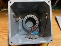
Ok, so I got Crowling's package in the mail, tested the cores, they are 43 mix cores. I tried to call Mr. Rowling but no answer. He hasn't answered my email yet either. So I wound a dual-core auto-transformer on these cores and tested it on my EFHW. I like the autotransformer if you're going to run power on one of these - it doesn't have overlapping windings and reduces chances of arc-thru between primary and secondary when running an amplifier.

Note: my EFHW is a vertical 127' wire and it has an extensive groundplane under it (34 radials) for use on 160. How the wire is oriented and proximity to ground will change results. I tested this first transformer with my IC-7300 rather than wasting time fiddling around with an analyzer.

IMG_1264.jpeg

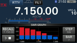
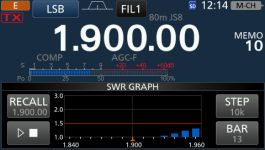
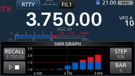
80/75 meters the results are exactly what I expected, the IC-7300's internal tuner will tune it fine across the whole band. I ragchewed with some guys on 3913 for an hour using this transformer at 1,000W on SSB. It worked fine with power on it, ran cool as the proverbial cucumber.

20250528_210057.png

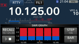
40 meters, this is what I get, and again exactly what I expected. The IC-7300's internal tuner will tune it fine across the whole band. I would limit power to 500 watts on 40m with this design because this is the upper limit of the frequency response for -43 cores when you have them stacked up.

20250528_210215.png

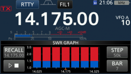
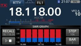
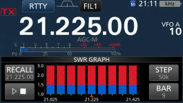
30 meters and on up to 15 meters, the IC-7300's internal tuner won't tune it, although my bigger external auto-tuner tunes it with no problem on any band. Starting at 30 meters you're already into the range where core losses are quite high. And while you can tune it up and it works, it is not a good antenna anymore once you get above 7300 KHz.

20250528_210444.png
20250528_210615.png
20250528_210758.png
20250528_211103.png

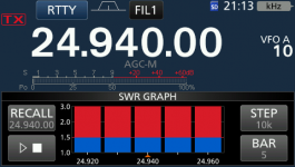
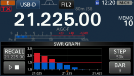
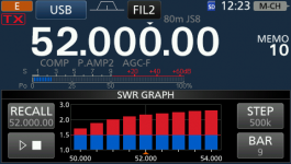
12 and 10 meters, because of the 100 pF capacitor, the IC-7300's internal tuner will tune it across both bands. The radio's SWR graphing feature shows it at 3:1 or greater on 12m, but the internal tuner tunes it fine. But I would not run more than 200W on it (SSB) on either of those bands because these cores are very lossy at these higher frequencies.

20250528_211320.png
20250528_211822.png

So I'll wait for Mr. Rowling to call me. With what he sent me, this is what he is going to get. -52's provide better high-frequency response, but not enough primary inductance for 80m (or 160) unless you stack a bunch of 'em up. The high permeability of the -43's is perfect for 80 meters where they will handle a lot of power with so low loss that it's not measurable. With a 160 EFHW you could stack up 3 or 4 of them and run full legal limit on them but I don't know of anybody that actually does that. On 160 1/4 wave verticals rule and nobody messes with EFHW's on that band. In fact, most people have compromise antennas on 160 - cloud burners, loaded verticals, whatever. On 80m, however, the venerable EFHW is pretty unbeatable as a vertical, really no different from a dipole as a horizontal (assuming you can get it high enough off earth ground).
 

Crowling

Member
Joined
Apr 9, 2022
Messages
50
Location
Spotsylvania Va
Ok, so I got Crowling's package in the mail, tested the cores, they are 43 mix cores. I tried to call Mr. Rowling but no answer. He hasn't answered my email yet either. So I wound a dual-core auto-transformer on these cores and tested it on my EFHW. I like the autotransformer if you're going to run power on one of these - it doesn't have overlapping windings and reduces chances of arc-thru between primary and secondary when running an amplifier.

Note: my EFHW is a vertical 127' wire and it has an extensive groundplane under it (34 radials) for use on 160. How the wire is oriented and proximity to ground will change results. I tested this first transformer with my IC-7300 rather than wasting time fiddling around with an analyzer.

View attachment 184395

80/75 meters the results are exactly what I expected, the IC-7300's internal tuner will tune it fine across the whole band. I ragchewed with some guys on 3913 for an hour using this transformer at 1,000W on SSB. It worked fine with power on it, ran cool as the proverbial cucumber.

View attachment 184394

40 meters, this is what I get, and again exactly what I expected. The IC-7300's internal tuner will tune it fine across the whole band. I would limit power to 500 watts on 40m with this design because this is the upper limit of the frequency response for -43 cores when you have them stacked up.

View attachment 184397

30 meters and on up to 15 meters, the IC-7300's internal tuner won't tune it, although my bigger external auto-tuner tunes it with no problem on any band. Starting at 30 meters you're already into the range where core losses are quite high. And while you can tune it up and it works, it is not a good antenna anymore once you get above 7300 KHz.

View attachment 184398
View attachment 184399
View attachment 184400
View attachment 184401

12 and 10 meters, because of the 100 pF capacitor, the IC-7300's internal tuner will tune it across both bands. The radio's SWR graphing feature shows it at 3:1 or greater on 12m, but the internal tuner tunes it fine. But I would not run more than 200W on it (SSB) on either of those bands because these cores are very lossy at these higher frequencies.

View attachment 184402
View attachment 184403

So I'll wait for Mr. Rowling to call me. With what he sent me, this is what he is going to get. -52's provide better high-frequency response, but not enough primary inductance for 80m (or 160) unless you stack a bunch of 'em up. The high permeability of the -43's is perfect for 80 meters where they will handle a lot of power with so low loss that it's not measurable. With a 160 EFHW you could stack up 3 or 4 of them and run full legal limit on them but I don't know of anybody that actually does that. On 160 1/4 wave verticals rule and nobody messes with EFHW's on that band. In fact, most people have compromise antennas on 160 - cloud burners, loaded verticals, whatever. On 80m, however, the venerable EFHW is pretty unbeatable as a vertical, really no different from a dipole as a horizontal (assuming you can get it high enough off earth ground).
I’m so sorry. I had ringer off today by accident. I normally turn it off at bedtime so if I sleep in it doesn’t wake me. I just saw your message but have not read it yet. I’ve been shopping today and just checking email and this site appears there when you post.
 

Crowling

Member
Joined
Apr 9, 2022
Messages
50
Location
Spotsylvania Va
Ok, so I got Crowling's package in the mail, tested the cores, they are 43 mix cores. I tried to call Mr. Rowling but no answer. He hasn't answered my email yet either. So I wound a dual-core auto-transformer on these cores and tested it on my EFHW. I like the autotransformer if you're going to run power on one of these - it doesn't have overlapping windings and reduces chances of arc-thru between primary and secondary when running an amplifier.

Note: my EFHW is a vertical 127' wire and it has an extensive groundplane under it (34 radials) for use on 160. How the wire is oriented and proximity to ground will change results. I tested this first transformer with my IC-7300 rather than wasting time fiddling around with an analyzer.

View attachment 184395

80/75 meters the results are exactly what I expected, the IC-7300's internal tuner will tune it fine across the whole band. I ragchewed with some guys on 3913 for an hour using this transformer at 1,000W on SSB. It worked fine with power on it, ran cool as the proverbial cucumber.

View attachment 184394

40 meters, this is what I get, and again exactly what I expected. The IC-7300's internal tuner will tune it fine across the whole band. I would limit power to 500 watts on 40m with this design because this is the upper limit of the frequency response for -43 cores when you have them stacked up.

View attachment 184397

30 meters and on up to 15 meters, the IC-7300's internal tuner won't tune it, although my bigger external auto-tuner tunes it with no problem on any band. Starting at 30 meters you're already into the range where core losses are quite high. And while you can tune it up and it works, it is not a good antenna anymore once you get above 7300 KHz.

View attachment 184398
View attachment 184399
View attachment 184400
View attachment 184401

12 and 10 meters, because of the 100 pF capacitor, the IC-7300's internal tuner will tune it across both bands. The radio's SWR graphing feature shows it at 3:1 or greater on 12m, but the internal tuner tunes it fine. But I would not run more than 200W on it (SSB) on either of those bands because these cores are very lossy at these higher frequencies.

View attachment 184402
View attachment 184403

So I'll wait for Mr. Rowling to call me. With what he sent me, this is what he is going to get. -52's provide better high-frequency response, but not enough primary inductance for 80m (or 160) unless you stack a bunch of 'em up. The high permeability of the -43's is perfect for 80 meters where they will handle a lot of power with so low loss that it's not measurable. With a 160 EFHW you could stack up 3 or 4 of them and run full legal limit on them but I don't know of anybody that actually does that. On 160 1/4 wave verticals rule and nobody messes with EFHW's on that band. In fact, most people have compromise antennas on 160 - cloud burners, loaded verticals, whatever. On 80m, however, the venerable EFHW is pretty unbeatable as a vertical, really no different from a dipole as a horizontal (assuming you can get it high enough off earth ground).
You don’t need to call unless you have questions I can’t answer here. I’m fine with you taking your time and experimenting with different types of unun’s. I was using the over under on primary and secondary. I used 3 cores stacked and had nothing higher than a 3+ swr but that was below 3.9mhz. I used 4 turns primary. Mine never got decent swr with using 3 turns primary. I tried to make a autotransformer but it had above 3+ swr.
 

Crowling

Member
Joined
Apr 9, 2022
Messages
50
Location
Spotsylvania Va
You don’t need to call unless you have questions I can’t answer here. I’m fine with you taking your time and experimenting with different types of unun’s. I was using the over under on primary and secondary. I used 3 cores stacked and had nothing higher than a 3+ swr but that was below 3.9mhz. I used 4 turns primary. Mine never got decent swr with using 3 turns primary. I tried to make a autotransformer but it had above 3+ swr.
There’s no rush at All ado it’s up to you as to how long you want to spend on it
 

AC9KH

Member
Joined
Nov 5, 2014
Messages
255
Location
Northern Wisconsin
I tried to make a autotransformer but it had above 3+ swr.

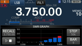
There shouldn't actually be any difference between an autotransformer or a regular winding as far as impedance matching. The only real difference is that the autotransformer doesn't have any primary winding overlapping with secondary where secondary can arc thru the enamel on the wire to the primary if you run an amplifier on it.
 

Crowling

Member
Joined
Apr 9, 2022
Messages
50
Location
Spotsylvania Va
There shouldn't actually be any difference between an autotransformer or a regular winding as far as impedance matching. The only real difference is that the autotransformer doesn't have any primary winding overlapping with secondary where secondary can arc thru the enamel on the wire to the primary if you run an amplifier on it.
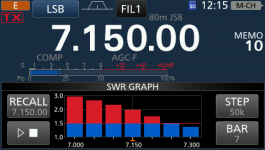
Right. I watched and tried making the auto Unun. Maybe experiment with 3 primary windings if you don’t mind. Let’s see if it brings the swr down to a reasonable measure
 

AC9KH

Member
Joined
Nov 5, 2014
Messages
255
Location
Northern Wisconsin
Here's my 80m EFHW. And this is with a radio applying power to the antenna, not a nanoVNA which will provide misleading results on antenna match with a transformer due to an analyzer not applying enough power to magnetize the transformer core.

Results are only marginally better on 80m than the test transformer I wound for Crowling because I have a 21 turn secondary instead of 14.

20250531_121515.png

40 meters, there's no difference.

20250531_121534.png

The rest of the bands are "close enough" so a decent external tuner will tune them just fine. That's assuming I'd actually use the antenna on those bands. Which I don't because it has too many radiation lobes and nulls at anything higher than 40 meters. I consider this a 160/80/75/40 meter antenna only.

And that brings up 160 meters. My antenna system has an advantage that most don't. This requires switching the transformer primary out, which converts it to a 1/4 wave Marconi. To get this to work you need two things - vertical polarization and an extensive ground radial system under the antenna. I have 34 in-ground 130 ft radials.

20250531_121449.png

Incidentally, switching the transformer primary out also works for 60, 30, 15 and 6 meters since all those bands are rough odd-1/4 wave multiples of the fundamental, electrically in the wire (electrical length, not physical length). You don't need a transformer at an odd 1/4 wave multiple - the feedpoint impedance is already low and the transformer just makes it worse than it has to be. Here's an example on 15 meters and 6 meters with the transformer primary switched out. The antenna is a perfect match on the upper end of 15 meters with the transformer switched out of the circuit with a relay. The antenna system will handle full legal limit power with the transformer switched out, with zero transformer losses because the transformer secondary is only used as a choke to isolate the "hot" and "ground" sides of the antenna. Plus it's DC grounded so it dissipates wind and rain static to earth ground instead of to the radio.

NOTE: Not sure this would work without a ground radial system under the antenna. And just because it works doesn't mean it's a good antenna on these bands. On 6m, for instance, the thing is twenty seven 1/4 waves long and on 15m it's eleven 1/4 waves long! It's got so many voltage and current nodes on it it looks like a centipede. Anything higher than 40 meters switch to something that puts out a decent radiation pattern.

20250531_122008.png

20250531_122342.png
 

AC9KH

Member
Joined
Nov 5, 2014
Messages
255
Location
Northern Wisconsin
So I wanted to try a transformer experiment comparing 52 mix cores to 43’s, except in a higher power transformer using three stacked cores. I went thru my parts drawers and I could only find one FT240-52, so I ordered two more, which came yesterday.

I wound two different windings and tested them, one test with 2/14 and the other with 3/21. I was not concerned with SWR results because SWR doesn’t mean anything. You can have a dummy load with good SWR. Turns out that’s what one of the configurations is - a dummy load. What I was more interested in is power dissipation or efficiency between the two.

So I set up a test using my 127’ vertical wire, RF power goes from the radio, thru the desktop tuner, down the 6’ feedline, thru the transformer and to the antenna. I measured the RF output power of the radio with a standard watt meter to make sure it puts out 100 watts running wide open, measured the power at the antenna with my Rigol spectrum analyzer with a RF current probe. The difference between the two is the loss in the matching network and feedline, with the only thing being changed from test to test being the transformer. I also tested 160m where the transformer primary is switched out with my antenna, but the transformer secondary is used - the inductive impedance isolates the driven and ground sides of the antenna.

I tested at 100W with a RTTY carrier, all tested at the center of each band. Note I did not test 30 or 15 meters because these two bands are odd 1/4 wave multiples of the fundamental, and switching the transformer out provides a better SWR match than leaving it in the circuit

Three FT240-43’s with 2/14 autotransformer winding:
160m - 96.4% efficient (3.6 watts dissipated)
80m - 91.9%
40m - 88.6%
20m - 67.5% (definitely don’t want to run an amplifier on this configuration on 20m)
10m - 66.4%

Three FT240-43’s with 3/21 autotransformer winding:
160m - 97.1% (adding more inductance to the secondary winding didn’t make a lot of difference here)
80m - 93.1% (approx -0.31 dB - this seems to be the sweet spot for this configuration)
40m - 89.1%
20m - 66.9% (definitely don’t want to run an amplifier on this configuration on 20m)
10m - 63.8%

Three FT240-52’s with 2/14 autotransformer winding:
160m - 66.8% (not enough inductive impedance in the transformer secondary here - power is not getting to the antenna)
80m - 70.8% (29.2 watts lost - definitely don’t want to use an amplifier here)
40m - 85.1%
20m - 86.9%
10m - 56.4% (this thing is a dummy load on 10m - dissipates just about half the power. Was not expecting this)

Three FT240-52’s with 3/21 autotransformer winding:
160m - 70.1% (still not enough inductance)
80m - 79.5%
40m - 86.7%
20m - 89.0% (this seems to be the sweet spot for this configuration)
10m - 55.8% (really no different from the 2/14 winding)

There’s not really much advantage to stacking up three vs two 43-mix cores. With just a single FT240-43 would probably get better results at 20 meters and above. These cores are pretty lossy above 7500 KHz, and the more you stack up, the more loss you will get at those frequencies. At lower frequencies there's more advantage to using higher inductance windings and I suspect if you test 2 vs 3 cores it's going to be about the same with the same winding type. And again, the less cores you use, the better it will be at the higher frequencies.

The 10m test with the FT240-52’s does not make sense. They claim a capacitor across the primary is supposed to help 10m so I soldered a 100 pF cap into it and tested it. SWR went down to 1.5:1 with the cap in there (vs 2.8:1 without it), but efficiency was worse - 46.2%. I concluded that this configuration on 10m is a dummy load. The skin effect @28 MHz on the transformer cores seems to be pretty pronounced. While the SWR is ok, it is not transferring power correctly @ 28 MHz, which indicates the transformer core is not working right at that frequency with the huge dropoff from 20 meters. While the FT240-43’s were not all that great at 28 MHz, and the SWR was considerably higher, they didn’t lose as much power as the -52’s. When they test these things they hook two back to back and use a little nanoVNA or something, then divide the loss results by 2. This is totally bogus and makes for good advertising. But put some power to it and measure in and out and you get real-world results that are closer to the real thing. Using the back to back and divide by 2 method yields bogus results because the cores aren’t “hot”. That would, at best, be a test for a QRP setup with maybe a couple watts on it. Tune it for best SWR @ 2W vs 50W, the tuning capacitance and inductance is totally different @ 50 watts.

The FT240-43’s seem to be the most versatile but the only band I would run an amplifer on is 80m (or 160 with the antenna configuration I have). On 40m could probably get by with it at 500 watts or so, but the transformer is still going to get hot dissipating over 100 watts with a 1KW amp on it. The FT240-52’s seem to be better around 20m with either winding type. But I still wouldn’t run an amplifier on this because you’re over 10% power dissipation. You could run 1,000 watts on this configuration with very limited duty cycle (SSB phone). With 100% duty cycle I’d keep the power below 200 watts. Note that the efficiency results may be different if you tune the wire for a particular band, say maybe a 66 ft wire for 40/20 meters. Testing losses using my method seems to indicate that you get best efficiency on only two bands with either core type or winding. Once you go outside that rather narrow range the efficiency seems to drop off quite dramatically with either one. Testing different wire lengths is a project for another day.
 

prcguy

Member
Joined
Jun 30, 2006
Messages
17,431
Location
So Cal - Richardson, TX - Tewksbury, MA
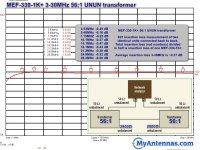
MyAntennas does not use 43 mix but they get low loss 80m through 10m like .5dB or less. You can connect two transformer secondaries together and measure insertion loss with a VNA or transmit through them and measure any power lost, then divide by two for single transformer loss. This is for one of their double stack cores and they may have similar info for their 3kW rated transformer.

8146A220-E14F-4BA1-91B1-7E72ECA05C4A.jpeg
 

prcguy

Member
Joined
Jun 30, 2006
Messages
17,431
Location
So Cal - Richardson, TX - Tewksbury, MA
They have a 5 to 30MHz 3kW rated transformer that has less then .25dB loss. They won’t divulge their core material.


MEF-530-3K-insertion-loss.png
 

AC9KH

Member
Joined
Nov 5, 2014
Messages
255
Location
Northern Wisconsin
They have a 5 to 30MHz 3kW rated transformer that has less then .25dB loss. They won’t divulge their core material.

The purpose of my test was to see what the efficiency is of the entire antenna matching system - tuner, feedline and transformer. Tune it up with the tuner so the radio puts out a full 100 watts. Test it to see what the total loss is ahead of the antenna. Then change the transformer out and and see how it changes. The results on 10m are rather disappointing and I'm not sure that's all in the transformer. The tuner may not be very efficient at 28 MHz. After I put the cap on the three-stack FT240-52's it lowered the SWR, but the reactive components of the complex impedance were quite high.

I want to test with wire cut for a higher frequency like either 40 or 20 meters using both transformers with the 3/21 winding. The 3/21 winding vs 2/14 seemed to provide better efficiency within the frequency range of each core type and it would be interesting to see if that still holds true with a shorter wire cut for resonance on one of the higher bands. The wire I'm using is 127', which is cut for best results on 160, 80/75 meters. It needs to be a bit longer to get better results on 40 and 20m, but I never use those bands on the EFW. To see how the efficiency is under full power on one of the higher bands it will be easier to test a wire cut for resonance on one of those bands than it will be to lengthen my existing wire.
 

AC9KH

Member
Joined
Nov 5, 2014
Messages
255
Location
Northern Wisconsin
MyAntennas does not use 43 mix but they get low loss 80m through 10m like .5dB or less. You can connect two transformer secondaries together and measure insertion loss with a VNA or transmit through them and measure any power lost, then divide by two for single transformer loss. This is for one of their double stack cores and they may have similar info for their 3kW rated transformer.

The trouble with that testing method is that you're not putting enough power to the transformer to get a good idea of dissipated power under load. Looks good on paper. Put power to it and you get different results.
 

prcguy

Member
Joined
Jun 30, 2006
Messages
17,431
Location
So Cal - Richardson, TX - Tewksbury, MA
The trouble with that testing method is that you're not putting enough power to the transformer to get a good idea of dissipated power under load. Looks good on paper. Put power to it and you get different results.
Not sure how the mfr tests the power rating but the 80-10m version is rated 1kW SSB and 250w for things like FT8. The 60m-10m version is rated 3kW SSB and 1kW FT8 and other long key down digital modes. You could test them with the same two in series setup used for loss testing with an 3kW 50 ohm load on the far end and just light them up with an amplifier or terminate one transformer with a 2.8k ohm non inductive resistor that will handle the power.
 

AC9KH

Member
Joined
Nov 5, 2014
Messages
255
Location
Northern Wisconsin
Not sure how the mfr tests the power rating but the 80-10m version is rated 1kW SSB and 250w for things like FT8.

Yeah, I think they use some intermittent rating. And it depends on the frequency and SWR. Anything over 2:1 that's tuned up is limited to like 200W on SSB. Like my dual core will handle 1KW on SSB with no problem on 75 or 160 meters as long as I'm not using speech compression in the radio on 75 meters. it will handle about 700 or so on the upper end of 40m, I consider 500 to be a safer limit on that band. Try that on 20m it will let the smoke out of it.
 

AC9KH

Member
Joined
Nov 5, 2014
Messages
255
Location
Northern Wisconsin
Not sure how the mfr tests the power rating but the 80-10m version is rated 1kW SSB and 250w for things like FT8

So I looked this up and the "rating" they use is ICAS. I don't know why they even use that because it's deceiving (probably deliberately). That rating is as old as the hills and used to be used for PA power tubes. Get rid of the ICAS deception, it's a 250w transformer that'll handle 1KW @ 50% duty cycle, mainly because the efficiency goes down the tubes once you saturate the transformer core.
 

prcguy

Member
Joined
Jun 30, 2006
Messages
17,431
Location
So Cal - Richardson, TX - Tewksbury, MA
So I looked this up and the "rating" they use is ICAS. I don't know why they even use that because it's deceiving (probably deliberately). That rating is as old as the hills and used to be used for PA power tubes. Get rid of the ICAS deception, it's a 250w transformer that'll handle 1KW @ 50% duty cycle, mainly because the efficiency goes down the tubes once you saturate the transformer core.
I have a number of MyAntennas transformers from about 200w through 2kW and have run 1200w SSB on the 1kW unit and it runs cool. I think they are rated conservatively otherwise they would be getting a lot of returns.
 
Top