Use this or just a simple splitter?

bigmac58

Member
Premium Subscriber
Joined
May 17, 2017
Messages
6
I’m running a discone antenna in my attic that’s feeding signal via RG6 to a scanner in my basement. I’m happy with the signal it receives and since I’m fairly close to most of the antennas that I’m trying to hear I would like to split the signal to feed another scanner I have upstairs. That radio is using the included telescopic antenna and I’m constantly adjusting it. This was left behind by the previous owner of my house and I’m curious to get thoughts if using it would help to overcome some of the loss caused by a splitter or it it could introduce noise onto the line. Thanks in advance!
 

Attachments

  • IMG_6930.jpeg
    IMG_6930.jpeg
    127.7 KB · Views: 50

vagrant

ker-muhj-uhn
Premium Subscriber
Joined
Nov 19, 2005
Messages
3,388
Location
California
It may overcome some loss and it may introduce noise. I don't know how many dB it offers, but you would adjust to max and then turn it down to lower your noise floor. If it is a 20 dB amp/splitter, I would not adjust it more than halfway, typically less. I would probably connect it near the upstairs scanner, which should have the shortest coax run. Then run the coax from it down to the scanner in the basement.

Anyways, before you connect the second run, listen to a particular frequency using one of the outputs and then switch outputs to ensure the signal levels, or at least it sounds the same. I could not find any information on that Radio Shack 15-1960C. If it does not work, you may want to take a look at the Electroline EDA-UG 2402. That Electroline has zero gain, but it should not introduce loss either.

You may introduce RFI due to the gain it offers, in particular from FM broadcast stations. See the URL in my signature for a thread that discusses various filters. If you do add filters, they would go inline before the splitter.
 

BinaryMode

Blonde Once Said To Call Her But Never Answerd
Joined
Jul 3, 2023
Messages
766
Location
75 parsecs this way -->
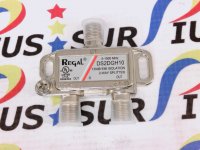
Right now I'm using a RegaL, UL listed two-way splitter with two handhelds. I can tell you that to my amazement I have not seen any drop in performance or signal strength at all for what I'm primarily interested in. But the air band seems to have suffered. In that, the guard frequencies of 121.5 and 243.0 don't come in all that well as they used to with two independent antennas. I'm principally monitoring two 800 MHz band towers using P25. Both scanners have a full quitting signal for these two towers according to the signal display in each scanner.

The setup is as follows:

Wide-band omnidirectional antenna outside about 10' in the air

Standard issue CATV coax fed into the house and then connected to the input of the splitter.

One the output of side A of the splitter is a F type to BNC adapter for one scanner.

On the output of side B of the splitter is a 6"- 9" cable (which I don't remember the type) where one end is a F type connector and the other is a SMA type connector that is connected to the scanner.

The two towers I monitor are about 8 miles away.


Depending on what you're monitoring and how good the signal is, it may suffice. I was exploring those drop amps and thought they would probably introduce noise, so just for testing I tried this splitter I had lying around and to my amazement it worked better than I thought it would. I thought I'd lose a bar or two in signal but that isn't the case.

This is the splitter I'm using.
 

Attachments

  • splitter.jpg
    splitter.jpg
    93.8 KB · Views: 3

cavmedic

Member
Premium Subscriber
Joined
Sep 2, 2012
Messages
770
Location
Pottstown Pa
A properly tuned OTA antenna pre amp is set up to compensate for any loss of feedline and splitter loss. When setup properly, you should have the same signal at the RCVR as you would have had without any splitter loss. Aka unity gain.

I have used CATV drop amps for years with great success on scanners, BUT I also measured the losses and added attenuators where needed after amplification and also added notch filters before the amp to eliminate paging and FM as those signals will over drive the amps.


A typical CATV drop amp will usually amplify between 25 MHZ and 1.2 GHZ to cover your downstream channel signals. But many will have return amps for cable modem upstream signals. Those usually reside between 5-45 MHZ but in newer systems called mid split systems, may have return upstream channels higher up in the spectrum.

So with bi-way amplifier, you can actually be radiating signals from your antenna.


Luckily that device is only a downstream amp and you should only be setting the gain factor of about 3.5 Db to compensate for the loss of the internal two port splitter and maybe about 1/2-1 sb more for that longer run.

RG6 typically has a loss of roughly 10db/100 foot at 800mhz, that amp is probably only rated to 600 MHz.


Also keep in mind, the specs for those would be measured in Dbmv as that the unit of measurement used in CATV
 
Last edited:

BinaryMode

Blonde Once Said To Call Her But Never Answerd
Joined
Jul 3, 2023
Messages
766
Location
75 parsecs this way -->
The upstream on a drop Amp will more than likely be 0 to a negative number dB as cable providers certainly don't want anything on the upstream interfering with their CMTS... 5-45 MHz is the frequency used for upload.

Addendum:

Since cable broadband uses hybrid fiber to coaxial, it's a shame modems (Modulator/Demodulator) can't output higher wattage and use amps along the lastmile to facilitate faster upload rates.

I for one am so glad I now have fiber. It's the best thing ever bar none. Very low latency, wicked sick jitter, high speed both up and down, and the GPON ("modem") is very simple electronics versus a cable modem and not requiring a ton of wattage from mains power. Which makes my backup UPS connected to all my equipment all the better in terms of backup power longevity. It's so great having fiber that I never want to live somewhere without it. It really is today's future for high speed Internet access and all of the above: TV and phone. Even though the technology has existed for decades. If I wanted to, and if I had the equipment, I could get up to 10 Gbps.
 

cavmedic

Member
Premium Subscriber
Joined
Sep 2, 2012
Messages
770
Location
Pottstown Pa
The upstream on a drop Amp will more than likely be 0 to a negative number dB as cable providers certainly don't want anything on the upstream interfering with their CMTS... 5-45 MHz is the frequency used for upload.

Addendum:

Since cable broadband uses hybrid fiber to coaxial, it's a shame modems (Modulator/Demodulator) can't output higher wattage and use amps along the lastmile to facilitate faster upload rates.

I for one am so glad I now have fiber. It's the best thing ever bar none. Very low latency, wicked sick jitter, high speed both up and down, and the GPON ("modem") is very simple electronics versus a cable modem and not requiring a ton of wattage from mains power. Which makes my backup UPS connected to all my equipment all the better in terms of backup power longevity. It's so great having fiber that I never want to live somewhere without it. It really is today's future for high speed Internet access and all of the above: TV and phone. Even though the technology has existed for decades. If I wanted to, and if I had the equipment, I could get up to 10 Gbps.
There are specific amps that have zero return gain , but there are some that do amplify. High return is just as bad as low forward levels. Every splitter port attenuates forward and return levels equally based on the loss of the splitter.
most of your major providers have or are switching to node +0 or node +1, significantly lowering the SNR when dealing with long amp cascades. And some are running G-PON and E-PON systems where its not feasible for a traditional HFC system.
 
Top