slowmover
Active Member
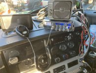
Semi-truck tractors come pre-wired with a fused 10A or 15A harness which connects to a standard radio cord via binding posts (in almost all cases).
Problem is that it’s both noisy (from fuse panel), and consists of a minimal wire gauge which allows for a greater than .5V (3%) volt drop while in use.
Chasing noise is ongoing. Quietest possible receive means an upgrade here is usually worthwhile. It’s a lot of work, however.
From Engine Off to Engine On there is usually some noise introduced with HVAC running and items inverter-powered being detectable:
I wouldn’t say it’s the amount or intensity base station operators encounter while at home, but the difficulty of an antenna ground plane (RF Bond) makes the following worthwhile, IMO. I’ve had to do it on the last (6) tractors I’ve driven.
Establish Radio Location & 12V Ground Point.
Negative
I’ve been able thus far (KW, Pete & FTL) to find a location to drill & use a stainless with screw plus lock washer & flat washers for 12V ground. Whether I’ve drilled thru the cab curtain track into the overhead console or used a right angle adapter, it’s a matter of easiest closest to the radio location. It’s not hard to find a place to drill that’s inconspicuous.
A). Test with meter.
B). Want to access it easily enough with radio in place (wire slack).
C). 1-2’ on average Neg length.
This ALONE can be adapted with the factory harness for fastest results if testing shows a difference. POS still from OEM, but new ground with new jumper installed between OEM & Radio cords.
Positive
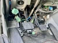
1). From the radio location, trace out the distance down the drivers A-pillar to the floor (except on Freightliner where one takes it down the passenger-side A-pillar).
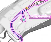
2). The cab wiring exit is the air line panel.
One will route through an unused hole. Study the exit from under the hood). Get the distance from radio to panel on interior; exactness not necessary.
3). From the panel exterior (underhood) the run is to the battery box under the drivers door via existing wire harnesses. I usually have to crank the Steer Tire hard to Starboard to access the space sufficiently to get this measurement (rough, but be generous).
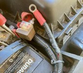
4). Now, from the battery box, the same exit for the power harness you traced to a 12V Battery Positive easy to reach plus some slack.
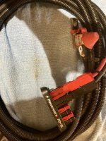
The average length of the fused Positive lead has been 18-19’ in my experience. So I suggest not buying less than 25’ to account for both Pos & Neg as it’ll be 20’ shortest for planning. Use entire 25’ to run the Pos as getting behind interior panels and making right-angle turns consumes length quickly.
In fact it’s “better”, IMO, to spec additional wire length to accommodate some noise filtering near the radio by wrapping several turns (as many as possible) through a large Mix 31 snap-over ferrite.
(Continued)


