hi
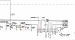
i have purchased ST-804A from com-spec.com and i want to install on GM 300 motorola , the below link is the link of installation instruction but really i got confused what to do , i know for many of you this is basic question but for me is a huge confusion .
i really appreciate if someone learn me how to install it .
http://www.com-spec.com/selectone/appnotes/8213.pdf
ready to pay consulting fee , indicating where to connect cables of module on the gm300 also helps alot
Regards
Last edited: