• To anyone looking to acquire commercial radio programming software:

    Please do not make requests for copies of radio programming software which is sold (or was sold) by the manufacturer for any monetary value. All requests will be deleted and a forum infraction issued. Making a request such as this is attempting to engage in software piracy and this forum cannot be involved or associated with this activity. The same goes for any private transaction via Private Message. Even if you attempt to engage in this activity in PM's we will still enforce the forum rules. Your PM's are not private and the administration has the right to read them if there's a hint to criminal activity.

    If you are having trouble legally obtaining software please state so. We do not want any hurt feelings when your vague post is mistaken for a free request. It is YOUR responsibility to properly word your request.

    To obtain Motorola software see the Sticky in the Motorola forum.

    The various other vendors often permit their dealers to sell the software online (i.e., Kenwood). Please use Google or some other search engine to find a dealer that sells the software. Typically each series or individual radio requires its own software package. Often the Kenwood software is less than $100 so don't be a cheapskate; just purchase it.

    For M/A Com/Harris/GE, etc: there are two software packages that program all current and past radios. One package is for conventional programming and the other for trunked programming. The trunked package is in upwards of $2,500. The conventional package is more reasonable though is still several hundred dollars. The benefit is you do not need multiple versions for each radio (unlike Motorola).

    This is a large and very visible forum. We cannot jeopardize the ability to provide the RadioReference services by allowing this activity to occur. Please respect this.

Using a VNA to tune a band-reject only duplexer

KD2DES

Member
Premium Subscriber
Joined
Nov 12, 2023
Messages
23
Location
New York, NY
I have a band-reject (notch filter) duplexer with low side at 462 MHz (transmitter) and high side at 467 MHz (receiver).
I would like to learn on how to tune a duplexer, so I’ve watched many tutorials on the use of a VNA. What I am having a hard time understanding is why S21 is connected to the antenna port and not to the opposite port of S11 (Low or High). I tried both ways and it seems that if I place S21 on the opposite port I get a complete picture of both notch filters and insertion loss. Whereas if I place S21 on the antenna port, I only see one notch filter. Am I missing something here?
 

prcguy

Member
Joined
Jun 30, 2006
Messages
15,385
Location
So Cal - Richardson, TX - Tewksbury, MA
I have a band-reject (notch filter) duplexer with low side at 462 MHz (transmitter) and high side at 467 MHz (receiver).
I would like to learn on how to tune a duplexer, so I’ve watched many tutorials on the use of a VNA. What I am having a hard time understanding is why S21 is connected to the antenna port and not to the opposite port of S11 (Low or High). I tried both ways and it seems that if I place S21 on the opposite port I get a complete picture of both notch filters and insertion loss. Whereas if I place S21 on the antenna port, I only see one notch filter. Am I missing something here?
For a two port VNA you would usually connect the S21 (source) port to the antenna side of the duplexer, connect the measure port of the VNA to the side of the duplexer you will be tweaking and place a 50 ohm load on the unused port. When done with one side of the duplexer move the VNA to the other side and put the 50 ohm load on the now unused port.

Many flatpack type notch only duplexers are rated around 75dB isolation max which is not that good but it can be at the dynamic range limits of a Nano VNA or similar. You want the VNA measurable dynamic range to be at least 10dB better than what you will be measuring and it will probably take a good bench top HP/Agilent or similar unit to make reliable measurements on a good duplexer.

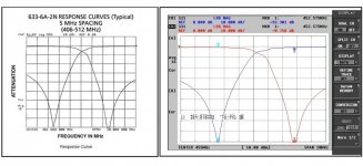
Also, connecting a VNA across both output ports of a duplexer, hopefully with a load on the antenna port, will let you see both sets of notches but at much reduced resolution. The max notch depth is very narrow and you want as much visibility and frequency accuracy on your VNA screen to adjust them to the precise needed frequencies and I like to keep the span less than 2MHz wide and usually about 1MHz wide when making the final adjustments. For a 5MHz spread you need 6 or 7MHz span to see both sets and you loose sight of the fine details of the notches. Once you get a set of notches in the ball park narrow up the span so you can see exactly what you are doing. And don't forget to check insertion loss from antenna port to each output before calling it a day.

Even with all that I have used some of my lower end two port Chinese antenna analyzers for a basic sanity check on a duplexer and to rough them in before fine tuning with a better instrument.
 
Last edited:

prcguy

Member
Joined
Jun 30, 2006
Messages
15,385
Location
So Cal - Richardson, TX - Tewksbury, MA
To add to my rant, I'll always calibrate my instrument at whatever wide span I'm starting with while herding all the notches together. Then I will narrow the span, which blows the calibration but I don't care as I'm just trying to line them all up with maximum notch depth at my target frequency. When its as good as it can get then I will recalibrate and get a precise measurement to see if it all meets specs. Doing this will speed up the tuning process without compromising the outcome.
 

KD2DES

Member
Premium Subscriber
Joined
Nov 12, 2023
Messages
23
Location
New York, NY
For a two port VNA you would usually connect the S21 (source) port to the antenna side of the duplexer, connect the measure port of the VNA to the side of the duplexer you will be tweaking and place a 50 ohm load on the unused port. When done with one side of the duplexer move the VNA to the other side and put the 50 ohm load on the now unused port.

Many flatpack type notch only duplexers are rated around 75dB isolation max which is not that good but it can be at the dynamic range limits of a Nano VNA or similar. You want the VNA measurable dynamic range to be at least 10dB better than what you will be measuring and it will probably take a good bench top HP/Agilent or similar unit to make reliable measurements on a good duplexer.

Even with all that I have used some of my lower end two port Chinese antenna analyzers for a basic sanity check on a duplexer.
Thank you for your reply. My VNA says S11 port is the source port (TX) and S21 is the measuring port (RX). Indeed I only see the notches if I turn on the S21 trace (S11 would only give me reflected signal). Here is the result when plugging S11 to Low and S21 to High with a 50 Ohms dummy load on the antenna.
I just don’t understand what’s wrong with this setup.
IMG_8973.jpeg
 

prcguy

Member
Joined
Jun 30, 2006
Messages
15,385
Location
So Cal - Richardson, TX - Tewksbury, MA
Thank you for your reply. My VNA says S11 port is the source port (TX) and S21 is the measuring port (RX). Indeed I only see the notches if I turn on the S21 trace (S11 would only give me reflected signal). Here is the result when plugging S11 to Low and S21 to High with a 50 Ohms dummy load on the antenna.
I just don’t understand what’s wrong with this setup.
View attachment 151329
With the display you have there is no indication of insertion loss, it appears you have about 18dB insertion loss because as you go from one set of notches to the other side which should be the low loss band pass side, you dive right into another set of notches. If you do just one side at a time and as an example you are starting with a 6MHz span showing the 462MHz notches and 467MHz pass at the same time and connecting only the antenna port and the low notch side of the duplexer with the high notch side terminated in a load. If you do this initially you will get the 462MHz notches in the ball park while seeing if any notch adjustment is pulling down on the 467MHz band pass. This is very important on a low cost flat pack as some notch adjustments will tug on the opposing band pass.

When you get the notches on one side in the ball park and no adjustments are pulling the opposite pass around you can then narrow the span to 2MHz or less and concentrate on getting the max notch depth at exactly the right frequency. Then and only then do you proceed to the other side of the duplexer and repeat the process.

Remember, there are two goals at the end, lowest possible insertion loss on the pass side and maximum notch depth on the notch side. You initially need an eyeball on both to make sure you aren't hosing your precious pass loss.
 

KD2DES

Member
Premium Subscriber
Joined
Nov 12, 2023
Messages
23
Location
New York, NY
With the display you have there is no indication of insertion loss, it appears you have about 18dB insertion loss because as you go from one set of notches to the other side which should be the low loss band pass side, you dive right into another set of notches. If you do just one side at a time and as an example you are starting with a 6MHz span showing the 462MHz notches and 467MHz pass at the same time and connecting only the antenna port and the low notch side of the duplexer with the high notch side terminated in a load. If you do this initially you will get the 462MHz notches in the ball park while seeing if any notch adjustment is pulling down on the 467MHz band pass. This is very important on a low cost flat pack as some notch adjustments will tug on the opposing band pass.

When you get the notches on one side in the ball park and no adjustments are pulling the opposite pass around you can then narrow the span to 2MHz or less and concentrate on getting the max notch depth at exactly the right frequency. Then and only then do you proceed to the other side of the duplexer and repeat the process.

Remember, there are two goals at the end, lowest possible insertion loss on the pass side and maximum notch depth on the notch side. You initially need an eyeball on both to make sure you aren't hosing your precious pass loss.
Amazing, thank you!
 

vagrant

ker-muhj-uhn
Premium Subscriber
Joined
Nov 19, 2005
Messages
3,187
Location
California
I used a $250 vector impedance analyzer N2061SA to dial in a flat pack duplexer and then used it with 50W. Loss was like 1.2 and no problem TX/RX from miles away during testing using handhelds. I was able to notch it around 75 to 80 dB. I checked it again once I had an HP 8935 a few months later. The sweep was so close, it wasn’t worth it to loosen the nuts and re-tune.

I do not have one of those NanoVNA’s. That $250 analyzer is much easier to use and I use it quite often. Even for building and tuning/sweeping antennas. Oh wow, it’s only $150 now on Amazon. I have a RigExpert and I use that N2061SA instead. It is also a bit smaller and lighter than the HP 8935. ;) @prcguy - thanks again for the heads up on that little analyzer five years ago.

For anyone still reading this, neither a NanoVNA nor my $250 N2061SA analyzer will tune a proper BpBr duplexer. You will chase ghosts. Ask me how I know. Ask me why I now have an HP 8935.
 

Ubbe

Member
Joined
Sep 8, 2006
Messages
9,055
Location
Stockholm, Sweden
Those S values means what port are source and what port are measure. Port one are usually the measuring port and port two the source and then it is called S21. If it is S11 the same port are used for both source and measure and you can only check what gets reflected back. You'll have to use a S21 setup to measure attenuation and insertion loss thru a device.

/Ubbe
 

xmo

Member
Joined
Aug 13, 2009
Messages
383
When tuning a duplexer, I always aim to have the analyzer's display match the manufacturer's spec sheet graph as closely as possible. That means setting the frequency span, reference level, etc the same as they did.

To illustrate, I have attached an image that shows both the spec sheet and the VNA results for a Celwave UHF flat pack duplexer.
 

Attachments

  • Celwave PD633 datasheet vs VNA.jpg
    Celwave PD633 datasheet vs VNA.jpg
    93.9 KB · Views: 24

freddaniel

Member
Joined
May 6, 2011
Messages
118
Location
Newport Beach, CA
Last but not least, remember to use jumper cables between the duplexer and radio made from double-shielded silver-plated cable like RG223, RG142 or RG214 for example. Plus use silver plated connectors on each end. If you don't, you may end up with 3 to 10 dB of desense.
 

rescue161

KE4FHH
Database Admin
Joined
Jun 5, 2002
Messages
3,638
Location
Hubert, NC
The silver connectors will tarnish and people think they are bad, because they are not nice and shiny, but trust me, the nice looking shiny plated connectors are not for repeater use.
 
Top