• To anyone looking to acquire commercial radio programming software:

    Please do not make requests for copies of radio programming software which is sold (or was sold) by the manufacturer for any monetary value. All requests will be deleted and a forum infraction issued. Making a request such as this is attempting to engage in software piracy and this forum cannot be involved or associated with this activity. The same goes for any private transaction via Private Message. Even if you attempt to engage in this activity in PM's we will still enforce the forum rules. Your PM's are not private and the administration has the right to read them if there's a hint to criminal activity.

    If you are having trouble legally obtaining software please state so. We do not want any hurt feelings when your vague post is mistaken for a free request. It is YOUR responsibility to properly word your request.

    To obtain Motorola software see the Sticky in the Motorola forum.

    The various other vendors often permit their dealers to sell the software online (i.e., Kenwood). Please use Google or some other search engine to find a dealer that sells the software. Typically each series or individual radio requires its own software package. Often the Kenwood software is less than $100 so don't be a cheapskate; just purchase it.

    For M/A Com/Harris/GE, etc: there are two software packages that program all current and past radios. One package is for conventional programming and the other for trunked programming. The trunked package is in upwards of $2,500. The conventional package is more reasonable though is still several hundred dollars. The benefit is you do not need multiple versions for each radio (unlike Motorola).

    This is a large and very visible forum. We cannot jeopardize the ability to provide the RadioReference services by allowing this activity to occur. Please respect this.

2018 Ford F150 supercrew install

Status
Not open for further replies.

CryptoBoy

Member
Joined
Dec 7, 2004
Messages
25
This will be a multi-part thread showing a multiple-radio install in a 2018 Ford F150 supercrew truck. It is primarily intended for future reference for those who need to do similar work. I have benefited greatly from these threads in the past and thought it high time I give something back. Although most of what I post will have been previously covered elsewhere, there are nonetheless some differences and new lessons to be learned.

I anticipate the following steps, and will post them as I get them completed:
1 - antennas
2 - power
3 - RF decks
4 - control heads

This post covers Step 1: antennas.

Given that this is the seventh F150 I've installed radios in, this step was pretty routine, although it was my first time with the aluminum roof. I should also mention that the other six F150s were XLT models (a mixture of supercab and supercrew) and this one is a Platinum, which is significantly different from the XLT, but not in ways that are important for this step (but will be in later steps).

One difference I immediately noticed was the coat hooks are a bit different than they were in 2014 (the last time I did this). It used to be that you stuck a screwdriver on top of the tab and flipped it down, revealing the torx screw underneath. Now that tab appears to simply pop off and you need to pry at it from the bottom instead of the top. Not a big deal, but it caused some confusion initially. Also, the tab comes completely off, and has to be snapped back in once you are done.

Another VERY important lesson learned has to do with the rear seat dome light assembly. It is clipped on the driver's side and connected to wires on the passenger's side. Whatever you do, do NOT disconnect those wires - you will never get them back together again. The correct procedure is to pull down gently on the driver's side, leaving the passenger's side alone. You want to drop the dome light, but only like a hinge, leaving it dangling from the head liner by the connected wires. Again, if you remove it (as I did), you will never get it hooked back up again because the wire is way too short.

In the interest of full disclosure, I did get it hooked back up, but then again I have extremely long arms. Most people could not reach as far as I could, and even I struggled to do this. I had to stick my arm in from the passenger side above the head liner and reach all the way to the dome light with my right arm holding the wire and connector, using my left arm to reattach the dome light assembly. Not fun. Just trust me on this: do NOT disconnect the dome light from its cable.

Drilling the holes and installing the NMO mounts was pretty much the same as it ever was. Measure four times and be extra sure of what you are doing. There's no fixing a mistake should you make one. I always put gaffers tape over the spot I'm going to drill, and start out with a pilot hole. I take plenty of time to make sure everything goes exactly according to plan. Of all the steps in an install, drilling is the most critical, so be sure to take extra time to get it right. Some folks might cringe at drilling holes in a $64K truck, but not me. I just made sure I didn't screw up.

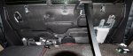
I use a steel snake to fish the coax, which might be more trouble than some would like to go to, but it has always worked for me. I stick the snake in from the hole and work it back to the dome light, then I tape a loose piece of scrap coax to the snake and pull it back out. Then I tape the real coax with the NMO mount attached to the scrap coax, and pull it back through the other way. Once at the dome light, I snake in from the driver's side above the headliner to the dome light, tape my coax to the snake, and pull it from the dome light to the driver's side above the rear door. From there, I feed it manually down the C pillar on the driver's side, making extra sure I clear the side airbags and all the other things that get in the way. You could probably use tape to hold the coax in place if necessary, but I didn't need to.

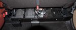
I pulled down the weather strip from the top center of the rear driver's side door to access the space above the head liner. I also loosened the trim panel that covers the C pillar so I could route the coax down the back corner of the cab. The easiest way to loosen the trim is to tug gently along the door until some of the clips release. The tough one is the top center clip which is very resistant to tugging, but which must come out. I do not remove the trim piece, but merely pull it loose up top. A flashlight helps considerably. I found a small notch at the bottom of the trim piece that was perfect to run the coax through. I also did everything with the rear seat folded down, which is easy to do on the F150 by using a box wrench to snag the pin that releases the seat latch. You can google this in case you've never done it before.

Once all three NMOs were in place and all the cables had been routed, I buttoned everything back up and set about installing the RF connectors. I always use RF Industries RFN-1000-1S N connectors, mostly just out of habit and because I hate crimp connectors (you have to solder the center pin on this one). I do the coax stripping with an xacto knife and spend a lot of time on this in order to get it exactly right without nicking anything, which comes from decades of doing this. I do recall 30 years ago being extremely frustrated when learning how to install N connectors (or BNCs, which I never use and neither should anyone else). It definitely is a skill like any other than you gain with much practice. I'm so old it's pretty much second nature to me, but it still takes time to do right. Don't be in a rush to do anything related to an antenna install.

Overall, installing the antennas was a relatively simple and straightforward task, save for the dome light fiasco which could have been avoided had I known better (another reason for posting that info here). It took me about four hours to do this task, but I took a couple of breaks, and I'm pretty slow because I want to be sure I don't make any mistakes.

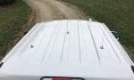
Here's the completed product, not that it's very interesting. Next up: providing power for the radios.
 

Attachments

  • antennas.jpg
    antennas.jpg
    74.6 KB · Views: 1,284

mmckenna

I ♥ Ø
Joined
Jul 27, 2005
Messages
23,618
Location
Hiding in a coffee shop.
Looking good. I did my 2011 F150 supercrew many years ago, but only 2 antennas, both centerline.
I've done a few F350's recently, 2017 and 2018, both aluminum bodies. Seemed like the aluminum was harder to drill than the steel, but just my feeling.
 

K7MFC

WRAA720
Joined
Nov 18, 2017
Messages
863
Location
Phx, AZ
I do the coax stripping with an xacto knife and spend a lot of time on this in order to get it exactly right without nicking anything, which comes from decades of doing this.

Why not use a coax stripping tool? Takes 2 seconds to get it perfect every time, and no danger of cutting yourself with an x-acto knife.
 

CryptoBoy

Member
Joined
Dec 7, 2004
Messages
25
A couple of notes during the intermission (I travel a lot, so I can only work on things for a few hours at a time and I'm still gathering goodies for connecting the power, which if I'm really lucky, I might get installed prior to my next trip on Wednesday).

Speaking of power, does anyone have any photos of where you can get good ground under the back seat in a newer (2015+) F150 supercrew? This would be very useful to me. As of now, my game plan is to run a separate ground wire (8awg) from the grounding point near the battery (yes, I am aware of the Ford bulletin about NOT running ground to the battery terminal), along with the hot wire, through the "nub" on that gasket on the passenger's side of the firewall (many thanks to those who posted pics of this). However, IF there is a decent ground point somewhere in the back, then why bother running an extra wire? Given that this truck has a ton of "junk" in it (premium sound system & power inverter) back behind the seat (and this is why this install is going to be REALLY tricky when it comes to mounting the RF decks), there has to be a decent ground around there somewhere. Anyone know precisely where?

Another thing that would be really helpful for me is if anyone has taken apart the center console (the "full length" one that has the shifter) and can tell me how to take it apart without breaking anything. It's always obvious after the fact, but sometimes you end up buying a new OEM part (at outrageous prices, typically) in the process of learning.

Mr. McKenna, I am a long-time fan of your installs and tutorials, which I first used on my 2012 F150 shortly after you posted your 2011. Great stuff for all and mostly why I'm posting this one. These things will turn up in searches years from now when folks are looking how to put a radio in a used truck they just bought (hint: buy one of mine and you won't have to do much because I leave everything in there except the RF decks and the control heads when I trade them in).

Mr. Callahan, I agree that your idea for stripping would be easier, but my experience with strippers has been less than ideal. We have several different varieties of strippers laying around the shop, but they never seem to work. Most are adjustable in one way or another, and none are ever adjusted properly. And then the blades always seem to be dull or broken, etc. I guess I'm just too old-school, in that when I was a punk fresh out of school (almost 40 years ago), an old hat showed me how to install connectors the hard-core way, combing out the braid and everything. I was horrid at first, but am pretty decent nowadays (aside from not being able to see very well or hold my hands still, things they don't include in your owner's manual). Besides, I don't mind taking 15min on each connector.

As I said, the power, though a fair amount of work, should be straightforward. The real tricky part is going to be mounting the RF decks and the control heads due to all the extra stuff on these high-end trucks (I know, I should have bought another XLT, but I'm getting soft in my old age and figure I better spend my coin before it ends up in probate). I'm going to have to get pretty clever on this one, and it might be a good deal more kludged than my installs of the past. For now I have initial operational capability using portables with speaker-mics hooked up to the antennas I installed, but that's just to get me by until I get this job finished. More to come...
 

mmckenna

I ♥ Ø
Joined
Jul 27, 2005
Messages
23,618
Location
Hiding in a coffee shop.
Mr. McKenna, I am a long-time fan of your installs and tutorials, which I first used on my 2012 F150 shortly after you posted your 2011. Great stuff for all and mostly why I'm posting this one. These things will turn up in searches years from now when folks are looking how to put a radio in a used truck they just bought (hint: buy one of mine and you won't have to do much because I leave everything in there except the RF decks and the control heads when I trade them in).

Thanks C.B.

Yeah, I've been doing it since the early 2000's. Getting a new vehicle then looking for install info. Not finding any, I'd figure it out, take photos, measurements, etc and post them. I think I've still got one or two sitting over on BatLabs, too.
Having something to work off of is really helpful, especially if the installs look good.

As for grounding…
On my 2011 F-150 and my 2018 F-350 I used a length of 13/16th thick UniStrut across the seat bolts. Mounted a piece of 3/4 ply to that and mounted the radios on the ply.
I didn't have to remove the seat mounting nuts, there was enough of the stud sticking up to allow the Unistrut to go over it along with a new nut (metric, can't recall the size…) I made sure the paint was off the studs, so I had a good ground through there. If you want, you can also put a lug in to the sheet metal behind the seat, the raised part is double walled. Use a self tapping screw. If you want yet more, install a couple. But I never had an issue using the seat mounting studs, they are welded to the body. Just make sure you deal with the paint.
 

CryptoBoy

Member
Joined
Dec 7, 2004
Messages
25
Step 2: Power

Just a few notes here on things I learned while doing this task. I'll save the pictures for Step 3.

The "nub" on the large gasket in the passenger's side firewall is already well documented in other threads, so I won't go into that, except to mention that my experience was slightly different, perhaps due to this truck being a Platinum instead of an XLT (I really don't know if that matters, but it might).

Here's how it went for me. I cut the end of the nub off with a razor knife, and sure enough, it revealed a hole big enough for a single #8 wire. But upon poking the wire into said hole, it only went in a couple of inches and then hit a dead-end. Not good. Upon poking a stiffer wire in this hole, it became apparent that this truck has a double firewall of sorts, with two gaskets: one in the engine compartment and another one in the passenger compartment. And of course there is no way to access the one in the passenger compartment due to all the "junk" that is crammed up underneath the dash and behind the glove box.

So here's what I did. In my installs of the past, I often penetrated a large rubber gasket in roughly the same place as the one in this 2018, but I don't recall the old ones having that "nub" sticking out. So back then I just punched a hole in them and ran my wires through there. But punching a hole in a thick rubber gasket is harder than it seems. Worst case you knock the gasket out of the fire wall and then have the fun task of trying to get it back in. I know, I've done that before and it's not easy.

So a long time ago, I built myself a special tool that you might find handy as well. It saved my butt this morning. Go to the hardware store and look at copper tubing and electrical wire. Find the size of tubing that is just big enough to pass a #8 wire (or whatever size you are using) through, but no bigger than this. You want the tube as small as possible, but big enough to stick the wire through. You need about 15" of this. Now get a saw and cut one end of the tube at a very shallow angle so the cut travels as far as possible down the length of the tube. You want this end to look like the end of a hypodermic needle, i.e. very sharp. After you cut it, file it down to make it as sharp as possible, preferable with the edges being razor sharp. You should easily be able to stab holes in things with it when you are done.

This tool, which I had made years ago, was what I used to penetrate the inner gasket on the new truck. I just poked it through the already cut off nub until it hit the inner gasket, then I twisted it around a bit to try and score the inner gasket somewhat, then I punched it on through. While the tool was still sticking through the gaskets, I ran my wire through the center of the tube, through both gaskets, and into the passenger compartment. From there it was a simple matter of pulling through the right amount of wire, then cutting it at the spool which was on the engine compartment side, then pulling the tool back out of the gaskets and off the cut end of the wire.

Routing the wire along the wire tray below the door trim was a simple matter that hasn't changed much since ancient times. Plastic pry tools are helpful because they make removing the trim pieces without damage a very simple task. Once the other end of the wire was in place behind the rear seat, I soldered a terminal lug on that end. The battery end got a 30-amp inline fuse very close to the battery, with a butt connector on one side and a terminal lug on the other.

I was planning to run a ground wire from the engine compartment to the back, but this seemed like way too much trouble, given the difficulty I had running the power wire through the firewall. My multimeter said I found a nice DC ground next to the woofer or whatever it is (part of the premium sound system) that takes up most of the room behind the center of the rear seat. We'll see how well it works once I get radios hooked up and operational. I may need to search further for a good ground, but let's hope not.

The finishing touch was a Blue Sea fuse box with six positions, positive and negative. I'll post photos once I get the radios connected and in place. That will be the really tricky part due to the fact that there is absolutely no room whatsoever behind the rear seat, and this is honestly something to think about (that I failed to) when buying a truck. If you're going to install radios, the high-end trucks are going to present you with quite the challenge because of all the factory installed "junk" that gets in your way and takes up all that free space you normally use for your radios. On the other hand, I think this is where I will end up either looking like a genius or an idiot depending on what I come up with. Stay tuned...
 

phask

Member
Premium Subscriber
Joined
Dec 19, 2002
Messages
3,670
Location
KZZV - SE Ohio
FWIW - Ford (probably other Mfg. as well) always publishes detailed info. on radio installs.


- Sorry, no link, but I have searched and found in previous years. Designed for pro's but well worth reading.

Many years ago my employer built wire harness for Ford's special fleet (police, commercial) vehicles.
 

mmckenna

I ♥ Ø
Joined
Jul 27, 2005
Messages
23,618
Location
Hiding in a coffee shop.
Some have mounted them on top of the dash in the center pocket. Not ideal, but an option. Easy to remove the rubber liner and drill a hole for cables.

Other option is inside the center console.
 

CryptoBoy

Member
Joined
Dec 7, 2004
Messages
25
Step 3: RF Decks

Now’s when the install gets interesting. As I mentioned in previous posts, the real problem with this install was the fact that Ford leaves you no room whatsoever in their higher-end F150s to add any sort of aftermarket accessories such as radios. Case in point, have a look at what’s behind that rear seat.

Interestingly, the passenger’s side of the rear seat has a nice tug strap on it that allows you to fold it down quite simply to reveal the tire jack, which you can see at the left side of the photo, filling the entire space from the rear cab wall to the back of the seat. The driver’s side uses the same latching mechanism that Ford has used for quite some time now, which is trivial to unlatch by lifting the seat bottom most of the way, looking behind the seat-back to eyeball the latch, then using the box-end of a wrench to snag the release pin and pop the latch.

Occupying the center section behind the seat is a large speaker connected to a voluminous plastic box, presumably a woofer of some sort. Not being an audiophile, I know little about these things. Nonetheless, whatever this thing is, it takes up roughly half the left-to-right area behind the seat, and like the jack, fills this space from front to back. The wires across the speaker are mine, a bit sloppy, I admit.

The driver’s side has what I believe to be the stereo amp, which is the large gray box at the right of the picture. Once again, it fills the space from front to back, leaving no room for RF decks, etc. To summarize then, any ideas about mounting RF decks behind the seat must be discarded because there simply is no room whatsoever. I don’t know for sure, but I suspect this is not the case for F150s with lower trims such as the XLT, etc. And once again I warn you not to make the same mistake I made, which is buying a high-trim F150 if you want to install radios in it.

Since behind the seat has been ruled out, the only possible place to mount the RF decks is the storage area under the driver’s side rear seat. This area isn’t very big, but I was able to jam everything in there that I needed, although just barely. I must say that I’m not especially proud of this install; it clearly isn’t my best work, but I was forced into it due to lack of other options. Here’s the result.
rfdecks

As it came from the factory, this storage area had a plastic trim piece across the front, held in place by four bolts. Not wanting to damage this piece (I will restore it when I sell this truck), I removed it and made a substitute out of 1x4 poplar that I painted black to make it less noticeable. It is the piece that runs horizontally across the bottom of the photo that has the two speakers attached to it. The three RF decks are also bolted to it, as you can see from the silver-colored screw heads (which I should paint black).

Believe it or not, there are five radios here: two TX/RX, and three RX-only. From left to right: VHF 110w, 700/800 35w, SDR dongle (just to the left of the seat belt), VHF portable RX-only, 900 RX-only. The three RX-only devices are used to receive telemetry, and interface to audio/data cables that run from behind the rear seat to under the driver’s seat (and ultimately to a USB interface box and on to a laptop PC). The two TX/RX radios have control heads on the driver’s side of the center console (to be shown in Part 4).

If you look carefully at the rat’s nest of crap to the right of the seat belt, you can see the Blue Sea fuse box and a 4-way antenna switch that is used to route a single antenna among three of the radios. It turns out that my use cases only require that three of the five radios to be active at any given time, thus allowing me to share antennas. I had hoped to avoid this, but it became apparent that five antennas was out of the question, so this was a reasonable compromise. Also, I originally planned on a second VHF RF deck, but since there was no room I opted for a portable with a battery-eliminator instead. As you can see, things just barely fit. And as I said, this is much messier than I would like, but I had little choice given what I had to work with.

The good news is that everything seems to work, and with the seat folded down there is no visible evidence of radios, aside from the antennas on the roof. I have yet to install the control heads for the two RF decks, but I did route the control cables, which was the most difficult task of all. Ford has gone to great lengths to make sure you can’t route cables from behind the rear seat to anywhere else. I’ll try to describe this in words; my apologies if it doesn’t make sense.

Starting at the rear wall of the cab, the carpet and insulation is very tight and there are only a couple of tiny places where you can even begin to lift it up. From here, there is a horizontal shelf about six inches wide, followed by a vertical cliff about four inches tall. In other words, from the rear wall forward there is a ledge that all the factory-installed stuff sits on (see picture above), and then at the front of this ledge the floor drops about four inches almost instantly. Then the floor becomes horizontal again for about one foot, roughly the area you see where the RF decks sit. Then there is this very nasty ridge that rises and falls abruptly and is about two inches wide. This is what makes routing the cables next to impossible.

I had one hell of a time running those control head cables. In past installs, I’d been so lucky as to poke control cables with connectors on them under the carpet, but this time I couldn’t even get my spring-steel snake to feed through there. I ended up pulling the driver’s side trim in the rear doorway and lifting the carpet from there. It was easy to snake from the door to under the driver’s seat, but it was still impossible to snake from the door to behind the rear seat.

Ultimately, I had to run my snake down the cliff behind the rear seat and into the flat space where the RF decks sit (under the carpet, of course). From there, it was not possible to snake any further due to that damn ridge I mentioned. So I reached in from the rear door with my arm under the carpet (note that I have exceptionally long arms), ran my hand over the ridge, grabbed the snake, and pulled it on through. That was the only way I was able to get the snake through. Once this was done, I taped some coax to the snake and pulled it back the other direction, and then poked the other end of the coax to the driver’s seat, leaving me with a piece of coax that now ran the route I wanted the control cables to run.

I must emphasize that this was the hardest part of the entire install; very painful and time consuming. And although I was able to use the coax to pull through two control cables and one audio/data cable, none of these had ends on them. I lucked out and found some really weird 10-conductor cable in a junk box, which I thought was Cat5 since it had RJ45s on both ends, but it had 5 pairs instead of 4 pairs and was really stiff, which was nice for my application. I cut the ends off and used this as my control head cable (which needed 10 conductors).

The tedious part was attaching connectors to both ends of the control cables after they had been routed under the carpet. You young people won’t think much about this, but splicing wires and soldering connectors with ten 26-guage wires is not easy when your eyesight is as bad as mine and your hands shake as much as mine do. Your owner’s manual doesn’t tell you about all the stuff that stops working once you turn 50, but beware. I would have spent half as much time on this install were I 20 years younger.

That’s all for Step 3. The final step is the control heads, which won’t amount to much. I’ll try to post that next week.
 

Attachments

  • behindseat.jpg
    behindseat.jpg
    70.7 KB · Views: 827
  • rfdecks.jpg
    rfdecks.jpg
    67.6 KB · Views: 825

jeepsandradios

Member
Feed Provider
Joined
Jul 29, 2012
Messages
2,005
Location
East of the Mississippi
The rear set has been an issue for a few years. Here is a slick latch if you do decide to use behind the seat. I have them on every truck i touch now -

https://www.builtrightind.com/products/builtright-industries-f-150-rear-seat-release

Also my new 2018 F150 was delivered Friday to me so this week I start drilling. Out of curiosity how does the center antenna look on the rib ? On my 2017 F150 I installed 2 antennas in the lower parts because the one antenna base appeared to be wider than the rib. I assume a standard 1/4 wave nut is fine there ?
 
Last edited:

CryptoBoy

Member
Joined
Dec 7, 2004
Messages
25
The center rib is a fine place for one or more antennas. McKenna was the first to show us the front-to-back channel under there that you can use to route cable through. Oddly, when I did this install, the cable did not come out of the channel like I thought it would, but it did come out at the rear dome light as I wanted it to, off to the driver's side of the channel.
I wanted to put 5 antennas up there, but that was simply too much for me to stomach, so I settled with 3. And given that you want at least a 1/4-wave radius around each antenna for ground plane, it made sense to put the VHF dead center. The others are offset so as not to interfere with the VHF pattern as much as possible.
On my previous truck, I only had 2 up top (and one on the driver's side hood lip, a non-ground-plane antenna) and they were both on that center rib, one center and one towards the rear.
I will caution you to probe the center channel of that rib once you lower the rear dome light, and be sure to heed my warning about removing it (just tug lightly down on the driver's side and let the passenger's side dangle from the wires). When you poke something through the hole into the front-to-back channel, you'll hit a solid cross piece about center of the roof. I made certain I was drilling behind this point because I don't know how to route the coax through that cross piece that blocks the channel. I'm sure it can be done, but I didn't want to mess with it.
 

RodStrong

Member
Joined
Nov 11, 2007
Messages
1,170
Location
West
I'd like to see a full pic of the truck at some point if you are willing
. Thanks.
 

mmckenna

I ♥ Ø
Joined
Jul 27, 2005
Messages
23,618
Location
Hiding in a coffee shop.
Mine was a 2011, and the ribs were narrower than those appear to be.
Even then, I had no issue with either the chrome nut style 1/4 wave antennas or the larger NMOq base Larsen antennas with the full gasket.
 

jeepsandradios

Member
Feed Provider
Joined
Jul 29, 2012
Messages
2,005
Location
East of the Mississippi
I was trying to mount the new all band antenna with my APX8500. It looked to be a bit wider than the rib at the base. The other antenna i needed to mount was the hockey puck for LTE so that needed to go between the ribs. I'll do some more measuring on the new truck today if it ever stops raining.
 
Status
Not open for further replies.
Top