40m, 20m, 15m and 10m dipoles

AussieLand

Newbie
Joined
Dec 16, 2023
Messages
4
40m, 20m, 15m and 10m dipoles: I am planning on stringing these up in paralell to each other and all centre fed from the one balun. The distance between each band wire will be about 1m

Will this work well? Is there an optimum (paralell) distance that they should be kept apart?

I only have 40m of land that I can string the 40m dipole in. Will this work on 80m and 160m? I can use an ATU for these bands.

Thanks for your help in advance.
 

hamstang

Member
Premium Subscriber
Joined
Feb 27, 2002
Messages
514
Location
Charlotte NC
40m, 20m, 15m and 10m dipoles: I am planning on stringing these up in paralell to each other and all centre fed from the one balun. The distance between each band wire will be about 1m

Will this work well? Is there an optimum (paralell) distance that they should be kept apart?

I only have 40m of land that I can string the 40m dipole in. Will this work on 80m and 160m? I can use an ATU for these bands.

Thanks for your help in advance.
From my experience, yes the 40m dipole will work on 80m and 160m. Receive should be quite good but you'll likely need to tune for transmit. Depending on your radio, the ATU may not be able to tune the dipole for 80 and 160. Newer HF rigs can only tune SWR from 3 to 1 while many older rigs have robust ATU's that can tune most anything.
 

AB5ID

Member
Joined
Aug 6, 2007
Messages
694
Location
Lee's Summit, MO (Kansas City)
40m, 20m, 15m and 10m dipoles: I am planning on stringing these up in paralell to each other and all centre fed from the one balun. The distance between each band wire will be about 1m

Will this work well? Is there an optimum (paralell) distance that they should be kept apart?

I only have 40m of land that I can string the 40m dipole in. Will this work on 80m and 160m? I can use an ATU for these bands.

Thanks for your help in advance.
You could put up the biggest dipole you can and feed it with ladder line that will work on all bands. Or maybe a horizontal sky loop. The fan dipole you are describing will work just fine it'll be hard to get the lower bands if it's cut for a half wave on 40 m.
 

AussieLand

Newbie
Joined
Dec 16, 2023
Messages
4
You could put up the biggest dipole you can and feed it with ladder line that will work on all bands. Or maybe a horizontal sky loop. The fan dipole you are describing will work just fine it'll be hard to get the lower bands if it's cut for a half wave on 40 m.
Where do I connect the ladder line to coax via balun?

You could put up the biggest dipole you can and feed it with ladder line that will work on all bands. Or maybe a horizontal sky loop. The fan dipole you are describing will work just fine it'll be hard to get the lower bands if it's cut for a half wave on 40 m.
What kind of copper wire should I use? I would like to use singe stand 1mm dia. copper wire, but I think this will be prone to breaking. Should I use multistrand insulated copper wire? what dia?
 

K3YGX

Member
Joined
Oct 4, 2014
Messages
41
Location
North Central Pennsylvania
I made a fan dipole for 40 (&15), 30, 20, and 10 meters center fed with RG8 -- it worked very well but I had to make some spacers to keep the wires from tangling up in the wind......but alas, the rope wore out and I could not replace it (couldn't reach the pulley) so I am now using a questionable vertical from eurocomm that is supposed to work 80-6 meters......I am not liking it much and want to put up my old R7
next spring. I could not load up on 75 or 80 with the dipole, I can with the vertical but it is just a dummy load, no one can hear me.

My dipole was made from 14 gauge wire, some heavy ceramic insulators all tied to a center piece with no balun to my antenna tuner.
I wish I could have fixed it but it was a one time thing with the mast up very high and no way to put another rope through the pulley.
 

AB5ID

Member
Joined
Aug 6, 2007
Messages
694
Location
Lee's Summit, MO (Kansas City)
Where do I connect the ladder line to coax via balun?


What kind of copper wire should I use? I would like to use singe stand 1mm dia. copper wire, but I think this will be prone to breaking. Should I use multistrand insulated copper wire? what dia?
You will need a balun and tuner to feed ladder line, or a balanced matchbox. Many tuners come with a built-in balun for ladder line. Ensure that the balun is positioned as close as possible to the tuner. The use of ladder line is helps because it eliminates the high losses associated with coaxial cable under high VSWR conditions.

Use any wire you like!
 

AussieLand

Newbie
Joined
Dec 16, 2023
Messages
4
In the same space as the proposed multiband dipole you can run a single length of wire (about 64ft) and feed it with a 49:1 balun for an easy resonant 40/20/15/10m end fed. No tuner should be needed with that. You can buy a commercial version, take it out of the package and be on the air in no time.
I've heard that dipoles have a better radiation pattern than long wire antennas and therefore get out better. Is this true?
 

prcguy

Member
Joined
Jun 30, 2006
Messages
15,385
Location
So Cal - Richardson, TX - Tewksbury, MA
I've heard that dipoles have a better radiation pattern than long wire antennas and therefore get out better. Is this true?
A 1/2 wave resonant dipole will radiate mostly broadside where a multiple half wave will have some gain lobes and nulls. I wouldn’t say a 1/2 wave dipole is better but you do need to understand the multiple half wave to make the best use of it.
 

devicelab

Whacker Extraordinaire
Joined
Jul 18, 2016
Messages
1,536
Location
Nowhere in WA
A 1/2 wave resonant dipole will radiate mostly broadside where a multiple half wave will have some gain lobes and nulls. I wouldn’t say a 1/2 wave dipole is better but you do need to understand the multiple half wave to make the best use of it.
Height also plays a large role too. If you can get [any] horizontal wire antenna up high then its performance really shines.
 

AC9BX

Member
Joined
Jun 11, 2011
Messages
333
Location
Lockport, IL
The wide-band dipole discussed here is called a doublet. This will be the largest dipole you can erect. It (probably) will not be resonant on any desired frequency and requires the use of a tuner. But when fed with ladder line the loss on the line will be low compared to coax. The ladder line is used for as much of the length as practical. Then an impedance transformer is used to attach to coax to feed inside and to the tuner. Some tuners will attach to ladder line directly. But getting ladder line indoors can be tricky. It doesn't want to be near anything conductive.

A 'fan' dipole will have a more narrow bandwidth on each band than a single wire dipole. They are somewhat difficult to tune because changes to one affect others. A meter spacing for the fan is good.

An off center fed dipole can be made resonant on several bands but it's VERY difficult to tune and will require a tuner as it will not match coax and will require a (voltage) balun as it is unbalanced and should not connect directly to coax or parallel line.

A sufficiently wide 40M will work quite well on 15M. The impedance will be somewhat higher on 15M. Depending on height above ground it may be acceptable without a tuner or other matching.

If you built something for 40/20/10, you can have 15 and it may work okay on 17 or 12 with the aid of a tuner.

Consider also a parasitic wire. This is a wire resonant on the desired frequency but is not connected to the driven antenna. It is close spaced. You will need a tuner or some matching to operate at that frequency but the parasitic wire will radiate well.

The more you try to squeeze out of a single antenna the less efficient it will be. But that's a widely varying situation and not as simple as I just stated. A dummy load can (and does) radiate, but it's terrible.

Band pass filters are useful, more cost involved of course. But you could set up 2 antennas on the same feed line, no switching required, and the signal goes into the correct antenna based on the frequency in use. This can be awkward however if you're trying to get 15M on the 40M wire for example. (The fan dipole essentially does this on its own.)
 

prcguy

Member
Joined
Jun 30, 2006
Messages
15,385
Location
So Cal - Richardson, TX - Tewksbury, MA
An off center fed dipole can be made resonant on several bands but it's VERY difficult to tune and will require a tuner as it will not match coax and will require a (voltage) balun as it is unbalanced and should not connect directly to coax or parallel line.
Your description of an OCFD is not realistic. My current main HF antenna at my house and for portable use is a MyAntennas 80-10m offset center fed and out of the box it covers all the phone portion of 80, 40, 30, 20, 17, 15, 12, and 10m without a tuner. I just connect my 1200w amp and transmit. It did not require tuning and is fed with 50ohm coax. It comes with an efficient 4:1 current balun and I also use a good 1:1 choke balun in the feedline. It’s the best performing out of countless HF wire antennas I’ve used over the last 30yrs.
 

AC9BX

Member
Joined
Jun 11, 2011
Messages
333
Location
Lockport, IL
It comes with an efficient 4:1 current balun
because it requires one. It will not match 50Ohm coax otherwise. Notice I used the word "directly."
Finding the exactly ideal feed point is very difficult to do at home. With a commercial model this is already done for you. Covering wider bands such as 80M generally requires a mixture of impedances above and below ideal. As long as they're within practical limits it's all good.
12M is easy with a fractional bandwidth of only .4. But 80M is difficult to cover with any antenna type having a fractional bandwidth of 13.3. Generally you get one end or the other including the OCFD. 17M rarely matches well.

4:1 will often be a voltage balun. The so-called 4:1 Guanella balun attempts to avoid transformer action by placing 2 coils in parallel. They can be efficient when using 2 cores because symmetric signals can pass through them with little loss instead of going in to the core, clever. But the common mode impedance is half of a simple 1:1 current balun.
A 1:1 choke balun is a current balun and this is required because it's an unbalanced antenna and you'll have common mode current on the feedline without it.

Depending on which side you're looking at, input versus output for transmitting or receiving, the 4:1 Guanella makes a transformation of double the voltage and half the current. It uses windings to induce current. This is transformer action and therefore describes a voltage balun. However, a goal is to produce equal voltages on the balanced terminals therefore describing a current balun. It's a strange critter.
 

prcguy

Member
Joined
Jun 30, 2006
Messages
15,385
Location
So Cal - Richardson, TX - Tewksbury, MA
Most OCFDs operate on a 1/2 wave fundamental frequency and also resonate with a good match on harmonically related bands. A 40m version would then be useable on 20, 15 and 10m. An 80m version is a bit different as 75m phone is not harmonically related to any other band so to get it to work on 40, 20, 15 and 10m the 80m resonant point will be down around 3.57MHz in the CW portion and the SWR in the 3.8 to 4MHz range will be high.

You can fix that by cutting the wire at the 1/2 way point and inserting a 150pf HV cap like a ”doorknob” and that will shift the 80m resonant point to cover 3.8 to 4.0MHz with a great match without affecting any other band.

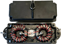
A typical point for the 4:1 balun according to most antenna books is about 30% from one end to get a good match on the fundamental and harmonic bands but MyAntennas used about 19% which gets a few more bands like 30, 17 and 12m with a useable match. They also use the dual core Guanella balun which is said to be the best type for an OCFD. Here is what their 4:1 balun looks like.

1703704375134.png
 
Last edited:

SV8OVZ

Newbie
Joined
Jan 3, 2024
Messages
1
Location
Limnos Isl. GR
Hello to all and happy new year!!!

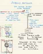
Trying to squeeze in my small QTH space a decent antenna for the 40-10m bands, i tried to combine an off centre wire antenna with something like endfed design and the result was the SV8OVZ antenna. In the SV8OVZ antenna there is a long wire element horizontally and the second element is the braided shield of a coax piece connecting the CMC with the transformer. The results are exceptional both for local and for DX comms given that one portion of the antenna is horizontally polarized and the second portion is vertical polarized, pushing the main lobe to a little bit smaller take off angles than the traditional OFC dipoles.


large.1764649510_SV8OVZWIREANTENNA.jpg.7cb97f7b5d0c21613f4cb6763d8045c5.jpg
 
Top