A Goubau Line

Joined
Jun 13, 2018
Messages
869
.


I have been meaning to write up this unusual topic for some time. Then a weather event this week brought it back in sharp focus with a snow storm and high winds. All night long this storm raged, and in the morning I was greeted by its twisted mass buried in a snow bank.
Caught your attention ? Well the twisted mess was a 600 foot run of #10 insulated wire that runs (ran :) ) from the peak of a barn up to the top of a towering granite escarpment that over-shadows my house. That escarpment was a wonderful shield against the elements for my great grand parents, but they built it long before there was any radio. It effectively puts me in a great semi-Faraday mountain cage for anything to the north.

That said, if I wanted to access any of the V/UHF ham repeaters in the valley to the north I would have to use a high gain antenna, swing it about to find the hot-spot on a mountain side --and bounce a signal out of my shadow.
I had thought of running a coax line up to the top of that escarpment, and put a beam up there, but the cable length with its feed line losses made that prohibitive.

Ah ! but what better reason to try a novel feedline- a Goubau line- than my "escarpment."

Better known as a "G-Line" (and no, that is not a "G-String" :) )- this feed line has been around since radio's beginnings. Yet it has been lost to time, at least to hams.

What is a G-Line ? ***

525px-Goubau.gif


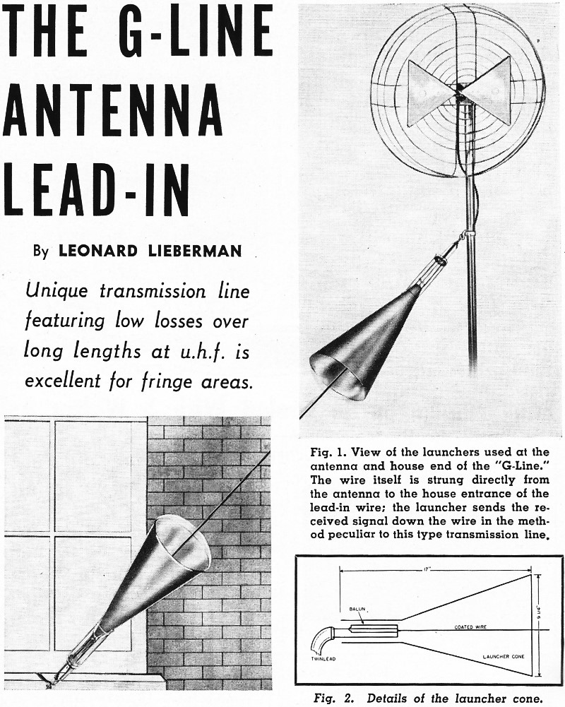
Simply put, its a single run of wire with two 'launchers' placed at both ends; it acts as a waveguide, and it is very effective at V/UHF frequencies. What is neat about this feed line is its extremely low losses--- while coax can be rated at so many dB's-loss per hundred feet, a G-Line is rated at so many dB's-loss per mile! ........The down size is they are just, really, mechanically, awkward..... This, making it pretty much a specialty item. But if its a situation requiring a lonnnng feed line run..........

In my case I was in luck to have some fellows at the machine shop at my lab fabricate the two launching horns for me. It took a bit of searching for the correct wire, for the dielectric on this wire acts much the same way to effect the forward wave like the earth's effect on low frequency "ground wave" signals.
The 'horns' terminate in standard 75 Ohm coax that feeds both the radio and a three-element commercial grade, wide bandwith beam.
We strung (and are going to have to re-string) -the wire by pulling it (Carefully!) taught with a tractor. It can tolerate some sagging, but it really wants to be straight. Sharp bends in the wire will induce losses, and also become radiation hot spots..

How does it work ?

Is Awesome a good technical term ?

_______________________________________________________________________________________________________________________________________________________-


I have no dB loss figures for this 600 foot run, but signals that were barely above the noise floor at the house (unless a beam was pointed at a mountain side as a passive repeater) -are 'full quieting" at the other end of the 'horn.'

Looking for an interesting project?


Lauri


----351kB.jpg


*** The 'G-Line' Community TV System, November 1956 Radio & Television News

.
 

MUTNAV

Active Member
Premium Subscriber
Joined
Jul 27, 2018
Messages
1,089
This was also in the 1997? version of the ARRL antenna book. They say that the "launching / receiving cone" should be at least 3 wavelengths long, and the line should be "large and heavily insulated".

I thought this was used more for microwave frequencies though. it works ok for V/UHF?

Thanks
Joel

(Haven't seen any pictures or trip reports from Svalbard btw. Or if there were any job offers ! ! )

:)
 

prcguy

Member
Joined
Jun 30, 2006
Messages
15,359
Location
So Cal - Richardson, TX - Tewksbury, MA
A long wire like that terminated properly will radiate some but will also have useful RF to tap at the end to feed coax. Besides the odd task of terminating the wire in a way that will efficiently transfer the RF there are probably multiple modes arriving out of phase and maybe the horns are suppressing some modes allowing an efficient transfer.

I‘ve used some unusual waveguide (Tallguide) that had extremely low loss for long runs of high power microwave transmission. It was basically a waveguide several sizes too big that would allow higher modes to propagate and tunable launchers are used at each end to suppress unwanted modes that would be out of phase and add loss. Maybe the G-line works in a similar way?
 

MUTNAV

Active Member
Premium Subscriber
Joined
Jul 27, 2018
Messages
1,089
I always imagined it as the alternating E-M field, kind of latching onto the more conductive wire (more conductive than air).
 
Joined
Jun 13, 2018
Messages
869
This is quite a technical issue and the following is the best explanation of a G-Line I can come up with. This is taken from the Radio & Television News, April 1955


--an unusual type of antenna lead-in which may be found useful for difficult v.h.f. installations is called "G-Line," after its inventor, Dr. G. Goubau. It is shown in Fig. 1. This new lead-in works on the surface-wave transmission principle.

It is well known that a single wire in air which has a voltage impressed on it will radiate energy. This, of course, is basic transmitting antenna theory. Dr. Goubau, in an effort to develop a simple super-high-frequency wave guide, found that when a single wire is coated with a dielectric material, some interesting things occur. The first of these is that the wire becomes nonradiating. As a result, virtually all the energy impressed at
one end of the wire is recovered at the other end---


.g-line-antenna.jpg

The second result noted is that as against the 72-ohm impedance of a coaxial cable of the same size, the impedance of the "G-Line" is approximately 300 ohms. This gives a better match to most antennas which are designed with a 300-ohm output impedance.

Another result is that since there is only one wire in the system, as compared to two in the twin-lead lead-in, the wire loss is half that of the twin-lead. A further benefit comes from the fact that just as the wire does not radiate, conversely, it cannot pick up external noises as might come from faulty electric motors, car ignitions, etc.

Figure 1 give a view of the launchers used at the antenna and house end of the "G-Line."The wire itself is strung directly from the antenna to the house entrance of the lead-in wire; the launcher sends the received signal down the wire in the method peculiar to this type transmission line. Figure 2 details the launcher cone.

To understand why these conditions prevail, let us examine the structure of the unit. If we consider the inner surface of the dielectric coating on the wire as one side of a capacitor and the outer surface as the other side, the amount of radiation would be a function of the leakage current through the dielectric. If the material has a good dielectric constant, this leakage is small and the radiation field is small. It has been found that this field can be kept within one-quarter wavelength from the center conductor.

The construction of the line makes it virtually unaffected by rain or layers of soot. In all two-wire systems, these installation bugaboos create low-impedance paths between the two lines. This is true to a greater or lesser extent of all two-wire systems. In the "G-Line," all that occurs is that the dielectric is increased with a very small increase in the loss resulting from additional dielectric currents. This effect is hardly measurable with laboratory-type equipment.

To develop the proper wave transmission along the line, special "launchers" are required. These launchers are hollow cones. The large diameter of the cone is determined by the desired size of the field around the wire and by the lowest operating frequency. (It might be noted that these launchers, because of the last-named requirement, also act as high-pass filters aiding the set in the rejection of interfering signals below the v.h.f. band.)

The launchers are 17 inches long and 914 inches in diameter at the large opening. A nonconducting cone is attached over this opening to keep the launcher weatherproof. The dielectric-covered wire is connected to a "balun" (balance-to-unbalance transformer). This balun has a flat standing-wave ratio over the entire u.h.f. band. The other end of the balun is connected to the short 300-ohm lead from the antenna, or the 300-ohm lead into the building.

The loss caused by the two launchers and the two baluns is approximately one db total and is constant over the entire v.h.f. band. The loss in the wire is 1 db per hundred feet. The dry loss in the best of the two-line systems is 1.9 db per hundred feet. Some elementary arithmetic shows that for runs over 125 feet with dry lines, the total loss of the "G-Line" becomes progressively smaller than the loss in the best two-wire system. When the comparison is made with new ribbon line of the type usually used, the "G-Line" is more efficient even for runs as short as 90 feet when dry and 30 feet when wet.

These facts indicate the potential of the "G-Line" in fringe reception areas. One of the limiting factors on the antenna tower height or distance from the house is the loss in the lead-in wire. This loss makes it inadvisable to take advantage of sturdy trees or a hill which might be more than a very short distance away.

With the "G-Line," it is possible to run the line from a point 300 to 500 feet from the house without any more loss than would be sustained with 100 feet of currently-used wire. Since the line is made with #14 AWG wire covered with 0.060" of polyethylene, it can be strung for as far as 500 feet without requiring any supports. If it is desired, the line can be supported by nylon string (such as used in fishing line) as long as the wire isn't bent more than 30° at any point. The launchers and wire are connected as shown in Fig. 1. The wire, itself, should be kept at least one foot from the house or the ground.


Lauri

7b8810408affc60625f9ec6fce9f36ac.jpg

.


Last edited:

MUTNAV

Active Member
Premium Subscriber
Joined
Jul 27, 2018
Messages
1,089
This is quite a technical issue and the following is the best explanation of a G-Line I can come up with. This is taken from the Radio & Television News, April 1955


--an unusual type of antenna lead-in which may be found useful for difficult v.h.f. installations is called "G-Line," after its inventor, Dr. G. Goubau. It is shown in Fig. 1. This new lead-in works on the surface-wave transmission principle.

It is well known that a single wire in air which has a voltage impressed on it will radiate energy. This, of course, is basic transmitting antenna theory. Dr. Goubau, in an effort to develop a simple super-high-frequency wave guide, found that when a single wire is coated with a dielectric material, some interesting things occur. The first of these is that the wire becomes nonradiating. As a result, virtually all the energy impressed at
one end of the wire is recovered at the other end---


.View attachment 138450

The second result noted is that as against the 72-ohm impedance of a coaxial cable of the same size, the impedance of the "G-Line" is approximately 300 ohms. This gives a better match to most antennas which are designed with a 300-ohm output impedance.

Another result is that since there is only one wire in the system, as compared to two in the twin-lead lead-in, the wire loss is half that of the twin-lead. A further benefit comes from the fact that just as the wire does not radiate, conversely, it cannot pick up external noises as might come from faulty electric motors, car ignitions, etc.

Figure 1 give a view of the launchers used at the antenna and house end of the "G-Line."The wire itself is strung directly from the antenna to the house entrance of the lead-in wire; the launcher sends the received signal down the wire in the method peculiar to this type transmission line. Figure 2 details the launcher cone.

To understand why these conditions prevail, let us examine the structure of the unit. If we consider the inner surface of the dielectric coating on the wire as one side of a capacitor and the outer surface as the other side, the amount of radiation would be a function of the leakage current through the dielectric. If the material has a good dielectric constant, this leakage is small and the radiation field is small. It has been found that this field can be kept within one-quarter wavelength from the center conductor.

The construction of the line makes it virtually unaffected by rain or layers of soot. In all two-wire systems, these installation bugaboos create low-impedance paths between the two lines. This is true to a greater or lesser extent of all two-wire systems. In the "G-Line," all that occurs is that the dielectric is increased with a very small increase in the loss resulting from additional dielectric currents. This effect is hardly measurable with laboratory-type equipment.

To develop the proper wave transmission along the line, special "launchers" are required. These launchers are hollow cones. The large diameter of the cone is determined by the desired size of the field around the wire and by the lowest operating frequency. (It might be noted that these launchers, because of the last-named requirement, also act as high-pass filters aiding the set in the rejection of interfering signals below the v.h.f. band.)

The launchers are 17 inches long and 914 inches in diameter at the large opening. A nonconducting cone is attached over this opening to keep the launcher weatherproof. The dielectric-covered wire is connected to a "balun" (balance-to-unbalance transformer). This balun has a flat standing-wave ratio over the entire u.h.f. band. The other end of the balun is connected to the short 300-ohm lead from the antenna, or the 300-ohm lead into the building.

The loss caused by the two launchers and the two baluns is approximately one db total and is constant over the entire v.h.f. band. The loss in the wire is 1 db per hundred feet. The dry loss in the best of the two-line systems is 1.9 db per hundred feet. Some elementary arithmetic shows that for runs over 125 feet with dry lines, the total loss of the "G-Line" becomes progressively smaller than the loss in the best two-wire system. When the comparison is made with new ribbon line of the type usually used, the "G-Line" is more efficient even for runs as short as 90 feet when dry and 30 feet when wet.

These facts indicate the potential of the "G-Line" in fringe reception areas. One of the limiting factors on the antenna tower height or distance from the house is the loss in the lead-in wire. This loss makes it inadvisable to take advantage of sturdy trees or a hill which might be more than a very short distance away.

With the "G-Line," it is possible to run the line from a point 300 to 500 feet from the house without any more loss than would be sustained with 100 feet of currently-used wire. Since the line is made with #14 AWG wire covered with 0.060" of polyethylene, it can be strung for as far as 500 feet without requiring any supports. If it is desired, the line can be supported by nylon string (such as used in fishing line) as long as the wire isn't bent more than 30° at any point. The launchers and wire are connected as shown in Fig. 1. The wire, itself, should be kept at least one foot from the house or the ground.


Lauri

View attachment 138452

.


I couldn't magnify the image with enough quality to get the detail of the cone...

Your article also explains the importance of the insulation (as did the ARRL book, they just said it should be heavily insulated vinyl.... I never thought that the insulation was actually important in a positive way for the propagation along the line.


Thanks
Joel
 
Joined
Jun 13, 2018
Messages
869
Errata---

I just re-read what I had copied and pasted above.... and would have laffed if I wasn't the serious scientific-type (grins ;) )

The diameter of the horns is NOT 914 inches ---76 feet........ mine are more like 28 inches, but I would have to measure them.


Geeeeez........ :(
 

MUTNAV

Active Member
Premium Subscriber
Joined
Jul 27, 2018
Messages
1,089
Errata---

I just re-read what I had copied and pasted above.... and would have laffed if I wasn't the serious scientific-type (grins ;) )

The diameter of the horns is NOT 914 inches ---76 feet........ mine are more like 28 inches, but I would have to measure them.


Geeeeez........ :(
Yeah, I was ignoring that part :)

Is it possible to re-scan the image and make the picture of the book page, showing dimensions larger?

Thanks
Joel
 

RFI-EMI-GUY

Member
Joined
Dec 22, 2013
Messages
6,877
I always found those old G line articles fascinating. It would seem there should be a niche market for them. For example, would the coupling loss be sufficient to use one as a leaky feeder in a tunnel radio system? Put cone launchers both ends, a repeater on one end and terminating resistor (or other antenna branch) at the far end?
 

prcguy

Member
Joined
Jun 30, 2006
Messages
15,359
Location
So Cal - Richardson, TX - Tewksbury, MA
Errata---

I just re-read what I had copied and pasted above.... and would have laffed if I wasn't the serious scientific-type (grins ;) )

The diameter of the horns is NOT 914 inches ---76 feet........ mine are more like 28 inches, but I would have to measure them.


Geeeeez........ :(
The pictures appear to show the length of the cones about twice as long as the diameter so if 17” long the dia could be 9ish inches.
 

MUTNAV

Active Member
Premium Subscriber
Joined
Jul 27, 2018
Messages
1,089
Thanks for the document....

I think we've all been saying the same thing.

My surprise is the importance of the insulator on the wire, I usually think of it as just protection OF the feedline or protection for other things FROM the feedline.

The part of the powerpoint slides that shows how there are problems if the alternating EM wave aren't allowed to fully develop, goes with the idea that the alternating E, then M wave, connect themselves (loosly speaking) to the wire.


Thanks
Joel
 
Joined
Jun 13, 2018
Messages
869
.

.............My surprise is the importance of the insulator on the wire, I usually think of it as just protection OF the feedline or protection for other things FROM the feedline.......

I agree, at first blush you'd think - "how is this important ?"--- but the G-line functions by slowing the propagation velocity of EM waves below the free-space velocity, which causes the wave front to slightly bend inwards towards the conductor;-- this keeps the wave contained. The dielectric coating slows the wave and focuses it along the wire. The line conducts energy via a one-dimensional electromagnetic surface wave, the same as the two-dimensional surface wave we call "ground waves."


........................Is it possible to re-scan the image and make the picture of the book page, showing dimensions larger?............

I tried but it came out too fuzzy. I think that instead of "914 inches" it should have been "9 1/4 inches" like prcguy deduced. This line apparently is for UHF television channels--- mine was (past tense for the the time being ?? :( )-- for lower frequencies.

Lauri


.
 
Last edited:

prcguy

Member
Joined
Jun 30, 2006
Messages
15,359
Location
So Cal - Richardson, TX - Tewksbury, MA
.

.............My surprise is the importance of the insulator on the wire, I usually think of it as just protection OF the feedline or protection for other things FROM the feedline.......

I agree, at first blush you'd think - "how is this important ?"--- but the G-line functions by slowing the propagation velocity of EM waves below the free-space velocity, which causes the wave front to slightly bend inwards towards the conductor;-- this keeps the wave contained. The dielectric coating slows the wave and focuses it along the wire. The line conducts energy via a one-dimensional electromagnetic surface wave, the same as the two-dimensional surface wave we call "ground waves."


........................Is it possible to re-scan the image and make the picture of the book page, showing dimensions larger?............

I tried but it came out too fuzzy. I think that instead of "914 inches" it should have been "9 1/4 inches" like prcguy deduced. This line apparently is for UHF television channels--- mine was (past tense for the the time being ?? :( )-- for lower frequencies.

Lauri


.
So for us cheaters I think we can assume the pictured system was designed for 470-806MHz and scale the cones to whatever we need.
 

tweiss3

Is it time for Coffee?
Premium Subscriber
Joined
Apr 24, 2020
Messages
1,077
Location
Ohio
Reminds me of RF microwave links.

I take it that wire sag is not an issue, it just "follows the wire"?
 

MUTNAV

Active Member
Premium Subscriber
Joined
Jul 27, 2018
Messages
1,089

MUTNAV

Active Member
Premium Subscriber
Joined
Jul 27, 2018
Messages
1,089
Unfortunately this thread has opened up a can of worms for me that literally kept me from going to sleep (like 3 am awake type).

Specifically,

1. The electric field aspect, the non-conductive insulation actually ends up confining the E-M wave to the line... Kind of against how I thought.

2. The impedence of free space is about 377 ohms.... I'm not sure how this fits into this, but it seems important.

3. Practical aspects may have to be altered for me.

I originally (in a future imaginary house) wanted a Rhombic antenna, (corner fed, kind of looks like a 2 dimensional cone launcher) that could be used as a loop skywire at lower frequncies, how much does the insulation value and apex angle of the radiating element effect the radiation (I realize the angle effects the pattern, but never considered the insulations effects, along with the insulations dielectric.?

I was considereing aireal cable with a messenger (steel) to keep the wire from drooping unexpectadly, I understood the steel would affect the radiation, but how much would the insulation effect radiation? I guess that's why people used copper clad wire?


Thanks
Joel
 
Last edited:

spanky15805

Newbie
Joined
Sep 18, 2004
Messages
306
Hold on a minute. Am I missing what the dielectric coating is? It is not insulation, right?

I keep thinking of some type "powder coating" or deposition layer on the wire.
 

MUTNAV

Active Member
Premium Subscriber
Joined
Jul 27, 2018
Messages
1,089
Hold on a minute. Am I missing what the dielectric coating is? It is not insulation, right?

I keep thinking of some type "powder coating" or deposition layer on the wire.
I'm taking it as the insulation being the dielectric, just like in a mica capacitor, the dielectric is the insulation between the plates...

Wild right? (or I could be wrong, I'm depending on Lauri-Coyote-Frostbite to correct my errors at this point)

In the ARRL antenna book (an older one), it says that its important for the line be large and heavily insulated, such as #14 vinyl insulated.


Thanks
Joel
 
Top