Adding Wire To Endfed SWL Antenna

Status
Not open for further replies.

prcguy

Member
Joined
Jun 30, 2006
Messages
15,368
Location
So Cal - Richardson, TX - Tewksbury, MA
The chart from Palomar seems to conflict with some known good designs and practices. Like Palomar says mix 52 and 61 are for common mode chokes starting above 200MHz but they have the best properties in the 25-30MHz range over mix 31, 43 and others.


.Prcguy....

..and here's a doc I found some time ago which rather put me off the "J" or 77 mix - and led me to use the 43 but even that's a compromise!

Ferrite Mix Selection - Palomar Engineers®
 

majoco

Stirrer
Joined
Dec 25, 2008
Messages
4,285
Location
New Zealand
Here's a bit of light bed-time reading.... :)

http://www.dxing.info/equipment/impedance_matching_bryant.pdf

...but it leads me to believe that a 77 or J would be a good mix for up to 7MHz and another antenna with my current un-un and breaker for 5MHz and up.

I'm just now looking through the real estate listings for a couple of acres on top of a hill out in the country in my price range with VDSL past the gate..... yeah right!


KB4MSZ

Billy
Premium Subscriber
Joined
Mar 12, 2018
Messages
932
Location
Tampa, Florida
I live in an apartment and, of course, I am quite restricted as to what I can do with HF activity. This applies to both SWL and amateur operations which include transmitting. Fortunately there is a tree at the head of my usual parking spot (when I get home early enough to capture it) that has a "Y" at about 12' off the ground. I use this to run a coax from my truck to my porch and then into my apartment in order to use my mobile antennas indoors. Thanks to the small diameter of the black RG-8X it hasn't been noticed by anyone so far.

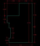
Using the outdoor resonant antennas as a reference, I compare them to my indoor wire divided "loop" which runs around the parameter of the living room and dining room of the apartment at just under the ceiling level. In most cases the mobile antennas out preform the "loop", but in a few exceptions the loop is very close to the same performance. In order to see this relationship graphically I ran a scan of the loop with my FA-VA5 antenna analyzer. The loop and it's dimensions are shown below.


The loop was cut open at the "tick" mark (red X) at the 1.5240 dimension, then folded down a few inches. Therefore it is not a closed loop. This is the half point of the length of wire around it's perimeter. The feed point is at the gap between the 5.0198 and 3.3688 dimensions, and it is connected to my SDRplay RSP2 via a short (12')run of RG-8X coax.

Loop Layout.jpg

The analyzer scan is shown below.

1.8 to 29.7 Open Loop Chart.jpg

Value List

Values.jpg

The main plots of interest are the SWR (red), complex impedance (blue), and the real impedance (black) relationships. There are some interesting occurrences of resonance with the antenna where the complex and real impedance come together and the reactance is canceled out, some of which where quite surprising to me such as 2.2MHz, 4.05MHz, 10MHz (not so surprising as the "loop" length is an exact full wave at 10MHz taking into account the velocity factor of the insulated wire), and 22MHz. I'm sure some of these points are due to the environment the antenna is installed in, not just it's dimensions. The listening performance with the SDRplay is in line with the chart at the frequencies where the antenna achieves resonance. Some of these resonance points are quite high in impedance but this could be, if desired, transformed by inserting the appropriate value balun when listening on these frequencies. I have temporary jumpers between certain points just to see what happens with the antenna's tuning, and this has produced quite a few interesting results. I have one jumper which, when installed, provides an unusually good coverage of the air traffic control band, despite being what I assume to be the wrong orientation. The top of the 75 meter phone band on the loop is very close to the performance of the 75 meter hamstick installed on my truck, as the chart shows with a 4.05MHz resonance. 15 meters is also very strong on the loop. The analyzer has allowed me to develop a number of combinations of good performance on desired frequencies quite easily. I recommend it very highly, especially for SWL.
 

ridgescan

Member
Joined
Apr 1, 2008
Messages
4,778
Location
San Francisco, Ca.
I live in an apartment and, of course, I am quite restricted as to what I can do with HF activity. This applies to both SWL and amateur operations which include transmitting. Fortunately there is a tree at the head of my usual parking spot (when I get home early enough to capture it) that has a "Y" at about 12' off the ground. I use this to run a coax from my truck to my porch and then into my apartment in order to use my mobile antennas indoors. Thanks to the small diameter of the black RG-8X it hasn't been noticed by anyone so far.

Using the outdoor resonant antennas as a reference, I compare them to my indoor wire divided "loop" which runs around the parameter of the living room and dining room of the apartment at just under the ceiling level. In most cases the mobile antennas out preform the "loop", but in a few exceptions the loop is very close to the same performance. In order to see this relationship graphically I ran a scan of the loop with my FA-VA5 antenna analyzer. The loop and it's dimensions are shown below.


The loop was cut open at the "tick" mark (red X) at the 1.5240 dimension, then folded down a few inches. Therefore it is not a closed loop. This is the half point of the length of wire around it's perimeter. The feed point is at the gap between the 5.0198 and 3.3688 dimensions, and it is connected to my SDRplay RSP2 via a short (12')run of RG-8X coax.

View attachment 72753

The analyzer scan is shown below.

View attachment 72752

Value List

View attachment 72755

The main plots of interest are the SWR (red), complex impedance (blue), and the real impedance (black) relationships. There are some interesting occurrences of resonance with the antenna where the complex and real impedance come together and the reactance is canceled out, some of which where quite surprising to me such as 2.2MHz, 4.05MHz, 10MHz (not so surprising as the "loop" length is an exact full wave at 10MHz taking into account the velocity factor of the insulated wire), and 22MHz. I'm sure some of these points are due to the environment the antenna is installed in, not just it's dimensions. The listening performance with the SDRplay is in line with the chart at the frequencies where the antenna achieves resonance. Some of these resonance points are quite high in impedance but this could be, if desired, transformed by inserting the appropriate value balun when listening on these frequencies. I have temporary jumpers between certain points just to see what happens with the antenna's tuning, and this has produced quite a few interesting results. I have one jumper which, when installed, provides an unusually good coverage of the air traffic control band, despite being what I assume to be the wrong orientation. The top of the 75 meter phone band on the loop is very close to the performance of the 75 meter hamstick installed on my truck, as the chart shows with a 4.05MHz resonance. 15 meters is also very strong on the loop. The analyzer has allowed me to develop a number of combinations of good performance on desired frequencies quite easily. I recommend it very highly, especially for SWL.
Wow you may be "restricted" by apartment living but you sure are making a go of it. I too live in an apartment here since 2002 but I am lucky in that I just went up there and installed my antennas one at a time and never got any orders to take them down. When the current owner of this building was here I told him about the antennas. He walked out and looked up there at the D130J and the Wellbrook loop and said I could keep them up there. He couldn't see the stealthy 100' endfed L wire along the east and north perimeters but it is the least visible of my three antennas anyway.
Been riding this wave for years now:)
 

a29zuk

Member
Joined
Mar 6, 2005
Messages
853
Location
SE Michigan
Speaking of rooftop antennas...when I worked in the foundry, many electricians in different departments, would put up antennas on the roof to watch TV between service calls.

As the radio guy in our department, I used a mobile mount wide range scanner antenna for others to watch TV. On top of the foundry we were up about 200 feet so it didn't take much. Everyone loved the great reception on the TV. For me, it would be for more, as I would hook up my Icom R-5 and listen to shortwave or listen to the local police calls.

The main problem was that management would go up there every so often and have them taken down.

That's when I had to get creative. There already was some electrical up on the roof for exhaust fans and other equipment. I found two junction boxes that were fairly close together. I ran some 3/4" rigid conduit from one box to the other but used two short threaded plastic pieces and couplings to insulate the dipole from the rest of the conduit. It looked like all the other conduits on the roof. A plastic coupling in the middle with a hole drilled in it to fish the RG-6 through completed the dipole. The antenna connection was taped up facing out toward the edge of the roof so no one would notice. The other end of coax was fed out through a T fitting in the stairwell under the roof and down to our work area.

The broadside of the dipole faced north/south. We could pick up the VHF-Lo TV channels 2-6 from over 100 miles away. Suffice to say that antenna stayed up there for five years until I transferred to another location. It is management proof and is probably still up there;)

Jim
 
Last edited:

ridgescan

Member
Joined
Apr 1, 2008
Messages
4,778
Location
San Francisco, Ca.
Speaking of rooftop antennas...when I worked in the foundry, many electricians in different departments, would put up antennas on the roof to watch TV between service calls.

As the radio guy in our department, I used a mobile mount wide range scanner antenna for others to watch TV. On top of the foundry we were up about 200 feet so it didn't take much. Everyone loved the great reception on the TV. For me, it would be for more, as I would hook up my Icom R-5 and listen to shortwave or listen to the local police calls.

The main problem was that management would go up there every so often and have them taken down.

That's when I had to get creative. There already was some electrical up on the roof for exhaust fans and other equipment. I found two junction boxes that were fairly close together. I ran some 3/4" rigid conduit from one box to the other but used two short threaded plastic pieces and couplings to insulate the dipole from the rest of the conduit. It looked like all the other conduits on the roof. A plastic coupling in the middle with a hole drilled in it to fish the RG-6 through completed the dipole. The antenna connection was taped up facing out toward the edge of the roof so no one would notice. The other end of coax was fed out through a T fitting in the stairwell under the roof and down to our work area.

The broadside of the dipole faced north/south. We could pick up the VHF-Lo TV channels 2-6 from over 100 miles away. Suffice to say that antenna stayed up there for five years until I transferred to another location. It is management proof and is probably still up there;)

Jim
I love it:) sneakin em in under the radar. What I like about my situation is by deploying those antennas and the owner actually giving them the nod, it proved that at least my antennas he saw, the discone and the loop, were not as "bad" nor as much of an "eyesore" as a layman's mind would have them presuppose they'd be resulting in a big fat NO.
 

ridgescan

Member
Joined
Apr 1, 2008
Messages
4,778
Location
San Francisco, Ca.
I think the time is ripe for you to quietly slip in your 10 meter EME dish.
If I knew what that was I probably would!
I'm moving into a new home in Rocklin, Ca. within 4 months soon as we find one we like so I couldn't get into more here anyway:)
It's going to be interesting come time for this shack's teardown. I even have to bring down the 9 cinder blocks somehow:( and then tearing down the I-80 in my truck with the antennas hanging half way out the tailgate. The SX-88 will be riding shotgun:LOL:
 

w8prr

Member
Premium Subscriber
Joined
Sep 23, 2005
Messages
276
Location
West Liberty, Ohio
Ridgescan, how did you mount the counterpoise? one the ground or in the air, and if so how far below the antenna?
 

ridgescan

Member
Joined
Apr 1, 2008
Messages
4,778
Location
San Francisco, Ca.
Ridgescan, how did you mount the counterpoise? one the ground or in the air, and if so how far below the antenna?
I shorted the two ground lugs on the PAR 9:1 trans, then I connected and ran the 45' counterpoise out parallel with the first half of the 100' antenna wire-about 3' underneath.
This is up on the roof at 35-40'.
 

questnz

Member
Joined
Nov 18, 2009
Messages
668
I also have (underused) PAR to be paired with SDR Play A1. I am reading with interest all this very good advice's on possible mods and improvements. Yet I like to hear from PAR Electronic themselfes what they actually think about it and how all this extensions may or may not improve reception on HF on stock 44 ft wire. Anybody actually asked them for comments yet?
 

ridgescan

Member
Joined
Apr 1, 2008
Messages
4,778
Location
San Francisco, Ca.
I also have (underused) PAR to be paired with SDR Play A1. I am reading with interest all this very good advice's on possible mods and improvements. Yet I like to hear from PAR Electronic themselfes what they actually think about it and how all this extensions may or may not improve reception on HF on stock 44 ft wire. Anybody actually asked them for comments yet?
This is right from Dale Parfitt in the instructions PDF.
As you read this you'll see they allow many variables for tailoring this system to your environment.
Personally, I can attest to better and more signals with a longer antenna wire on the PAR box.


ASSEMBLY 1. The antenna comes assembled. The user must make 2 decisions: A. How to hang the antenna– either horizontally, as a sloper, vertically, or as an inverted vee. Some polar plots are included to help you with this decision. The sloper is our favorite as it allows for a very short RF ground at the antenna. Remember, if a ground wire is 1/4 wavelength long– it is virtually invisible. B. How to configure the grounding. This will vary from location to location. The 9:1 binocular core transformer has both the primary and secondary ground leads brought out to 10-32 stainless studs. See Fig. 2. Default is with these two connections (#1-#2) shorted and attached to an RF ground close to the matchbox . This connection may also be left ungrounded and then grounded at the receiver. However, this connection may result in noise pick up on the shield of the coax. Depending on the efficacy of the receiver ground, more noise may be present with this connection, and the outer shield may also act as part of the antenna. Alternatively, the shorting connection may be removed and the antenna side grounded at the antenna (#2), the receiver side (#1) may then be grounded back at the receiver location, or left ungrounded– whichever results in less man made noise pick up . The thought here is that noise generated in the home (dimmers, fluorescent lights etc) can be conducted along the coax to the antenna. This is the instance at my listening location. This may be especially true if your antenna is located a distance from the home. When making comparisons, do not judge by the S meter– but rather, choose weak stations on a number of different frequencies. C. A good RF ground may be provided at the antenna and/or at the receiver by use of a 6’ copper clad ground rod intended for electrical grounds. These are commonly available at any of the home construction stores like Lowes or Home Depot
 

questnz

Member
Joined
Nov 18, 2009
Messages
668
Oh thank you ridgescan it make sense, I was more interested in the extra length of wire as an extension and how much extra would be optimal.
In my case it is horizontal arrangement, transformer is screwed to windows frame and wire going outside to closest tree. Can I see any great performance improvement with extra extention eg from end of existing antenna attached to the tree then back to the house corner. It would make about 90 deg angle with another 40-50 ft or so.
 

ridgescan

Member
Joined
Apr 1, 2008
Messages
4,778
Location
San Francisco, Ca.
Oh thank you ridgescan it make sense, I was more interested in the extra length of wire as an extension and how much extra would be optimal.
In my case it is horizontal arrangement, transformer is screwed to windows frame and wire going outside to closest tree. Can I see any great performance improvement with extra extention eg from end of existing antenna attached to the tree then back to the house corner. It would make about 90 deg angle with another 40-50 ft or so.
Experiment:) that's what I did. Try it out and see what it'll get ya. Personally, I prefer one continuous unbroken wire but hey, if you can connect the extra wire WELL at the far end it's worth a try.
 

questnz

Member
Joined
Nov 18, 2009
Messages
668
Thank you both, the learning never stops. Two more dumb questions from HF green wannabe if I may. :unsure:
1. I assume that the bit on end of the PAR is a conductive and extra wire need to be attached to it.
2. What sort of wire to be used for "optimum" match with existing wire.
 

WA8ZTZ

Member
Joined
Feb 23, 2014
Messages
977
Location
S.E. MI
Thank you both, the learning never stops. Two more dumb questions from HF green wannabe if I may. :unsure:
1. I assume that the bit on end of the PAR is a conductive and extra wire need to be attached to it.
2. What sort of wire to be used for "optimum" match with existing wire.

The "bit" on the end that you refer to is probably the insulator.
If you wish to add extra wire, you will have to remove the insulator and splice on to the end of the original wire.
IIRC, the original wire on mine was #18 polystealth.

An improperly made splice could be problematic... perhaps a better
approach would be running all new wire.
 

ridgescan

Member
Joined
Apr 1, 2008
Messages
4,778
Location
San Francisco, Ca.
The "bit" on the end that you refer to is probably the insulator.
If you wish to add extra wire, you will have to remove the insulator and splice on to the end of the original wire.
IIRC, the original wire on mine was #18 polystealth.

An improperly made splice could be problematic... perhaps a better
approach would be running all new wire
.
Exactly!
 

ridgescan

Member
Joined
Apr 1, 2008
Messages
4,778
Location
San Francisco, Ca.
If the right amount is correct, then more is better and too much is just right..... :unsure:
Martin I went up there today and did some experimenting. I got the new 100' roll of #12 solid coated wire and ran a full 100' counterpoise parallel with the 100' L antenna, 2' underneath the antenna wire. NOT good. Cut all signals across MW and SW in half-seemed to really weaken reception.
So I used 45' of that new wire and replaced the stranded wire I originally put up for counterpoise. Much better:)
So in the case of my counterpoise-too much was just wrong:whistle: but at least it showed me that your counterpoise advice was dead-on and that CP is indeed effective.
 
Status
Not open for further replies.
Top