Antenna in the Attic and Coax question.

Status
Not open for further replies.

fredva

Member
Feed Provider
Joined
Mar 19, 2007
Messages
2,225
Location
Virginia/West Virginia
What do you mean by sounding kinda weak? Soft or Noisy?

I would test out a regular splitter to see if you really need an amplifier.

Most amplifiers other than ones designed as receiver pre-amps are noisier then the receiver front end, and actually decrease sensitivity.

Weak as in soft or low volume. My relatives live in a hilly area. They have a public safety tower about 3 miles away and another one about 10 miles away. The desire is to listen to both of these. Currently the tower 3 miles away comes in loud and clear while the one that is 10 miles away has a lower volume. A couple of years ago, we had to raise the external antenna at the house an additional 10 feet in order to continue receiving the tower that is 10 miles away.

I'm not an expert on radio communications, but in my mind, it seems they are doing well to pick up the more distant tower as it is, and if you divide the existing signal in two with a passive splitter, plus add another 50 ft or so of cable over to the second scanner, it seems there is a high risk that one or both scanners would not pick up the more distant tower. Am I wrong?

There are other towers that are also desired listening, but I think the two I mentioned are enough to illustrate the scenario.
 
N

N_Jay

Guest
Weak as in soft or low volume.
On an FM radio weak signal are not soft, they are noisy.

The soft ones are probably just narrow-band or poorly trained users.

My relatives live in a hilly area. They have a public safety tower about 3 miles away and another one about 10 miles away. The desire is to listen to both of these. Currently the tower 3 miles away comes in loud and clear while the one that is 10 miles away has a lower volume.
It sounds like the further system is narrow-banded and the close one has not yet.

A couple of years ago, we had to raise the external antenna at the house an additional 10 feet in order to continue receiving the tower that is 10 miles away.
Sounds like you already did what was needed to receive the system. If going up 10 feet made the difference between not hearing it and hearing it, I would go up another 10 feet. Bet you will get back more signal than you will lose in the splitter.

I'm not an expert on radio communications, but in my mind, it seems they are doing well to pick up the more distant tower as it is, and if you divide the existing signal in two with a passive splitter, plus add another 50 ft or so of cable over to the second scanner, it seems there is a high risk that one or both scanners would not pick up the more distant tower. Am I wrong?
There is a very good chance you are.

Does the scanner have a 20 dB attenuator or pad button? What happens when you push it?

You could just get a 4 way splitter and see if that kills the signal. If it doesn't then you are fine with a 2 way and the extra cable.

There are other towers that are also desired listening, but I think the two I mentioned are enough to illustrate the scenario.
Maybe, maybe not. FM radio hides any extra signal from you so you rarely know if you are on the edge or have tons of extra signal.
 

jackj

Member
Joined
Jul 19, 2007
Messages
1,548
Location
NW Ohio
Splitter?

Weak as in soft or low volume. My relatives live in a hilly area. They have a public safety tower about 3 miles away and another one about 10 miles away. The desire is to listen to both of these. Currently the tower 3 miles away comes in loud and clear while the one that is 10 miles away has a lower volume. A couple of years ago, we had to raise the external antenna at the house an additional 10 feet in order to continue receiving the tower that is 10 miles away.

I'm not an expert on radio communications, but in my mind, it seems they are doing well to pick up the more distant tower as it is, and if you divide the existing signal in two with a passive splitter, plus add another 50 ft or so of cable over to the second scanner, it seems there is a high risk that one or both scanners would not pick up the more distant tower. Am I wrong?

There are other towers that are also desired listening, but I think the two I mentioned are enough to illustrate the scenario.


You don't mention what band you want to monitor so I'm going to give you some ballpark info. A 2 port splitter will have around 3.25 db of loss at 150 Mhz. 50 feet of cable will range from about 3 to 1.5 db of loss, depending on what type of cable. So you are looking at somewhere between 4 to 6 db of loss. At 6 db, each scanner will receive about 25% of the signal at the input port on the splitter. A 3 db loss is 1/2 the signal so yes, if your signal is noisy now you might not receive anything using just a splitter. The loss figures are worse at 450 Mhz and become much worse if we are talking about 800 Mhz.

If you go with a pre-amp then get one that mounts at the antenna and has somewhere around 10 db or more gain plus it will have to cover the frequency you want to monitor. You mentioned in an earlier post that you had a transmitter about 1.5 miles away, that should be far enough away that it won't cause problems with a quality pre-amp. Most pre-amps can't put out enough signal to block the front end of a good scanner because their input will saturate before reaching that point.

If you decide to use a distribution amp or an amplified splitter bear in mind that most of them only make up for losses in the splitter. They will not give you any extra gain to make up for cable loss or to boost weak signals. Get one that is designed for off-the-air TV and not cable TV. The off-the-air type will handle weaker signals and have a lower noise figure.

I wouldn't worry about trying to get another 10 or 20 feet of antenna height. The gain in signal will be marginal to nonexistent unless your antenna is in the shadow of trees or some other structure. Good luck getting the system up and running.
 

fredva

Member
Feed Provider
Joined
Mar 19, 2007
Messages
2,225
Location
Virginia/West Virginia
options

Don't know about the narrow-banding on the tower.

As far as raising the antenna higher, I'm not sure how high they want the antenna towering over their house. Another 5 foot might be OK, but maybe not 10.

My PRO-2052 doesn't have the attentuator button on it, so I doubt their PRO-2050 does either. I'm sure the 80's model PRO-2020 to be used as the second scanner doesn't either.

They live in another state, so it's not as easy for me to try out different things as it would be if I was doing this in my own home. Ideally I would have all the equipment needed for the setup the next time I go for a visit.

If a passive splitter would work that would be great because of the low cost and no need to plug in yet another device. I was considering the drop amp because of the postive things said about them on this thread: http://forums.radioreference.com/antennas-coax-forum/105054-using-one-antenna-multiple-scanners.html
 

fredva

Member
Feed Provider
Joined
Mar 19, 2007
Messages
2,225
Location
Virginia/West Virginia
You don't mention what band you want to monitor so I'm going to give you some ballpark info. A 2 port splitter will have around 3.25 db of loss at 150 Mhz. 50 feet of cable will range from about 3 to 1.5 db of loss, depending on what type of cable. So you are looking at somewhere between 4 to 6 db of loss. At 6 db, each scanner will receive about 25% of the signal at the input port on the splitter. A 3 db loss is 1/2 the signal so yes, if your signal is noisy now you might not receive anything using just a splitter. The loss figures are worse at 450 Mhz and become much worse if we are talking about 800 Mhz.

If you go with a pre-amp then get one that mounts at the antenna and has somewhere around 10 db or more gain plus it will have to cover the frequency you want to monitor. You mentioned in an earlier post that you had a transmitter about 1.5 miles away, that should be far enough away that it won't cause problems with a quality pre-amp. Most pre-amps can't put out enough signal to block the front end of a good scanner because their input will saturate before reaching that point.

If you decide to use a distribution amp or an amplified splitter bear in mind that most of them only make up for losses in the splitter. They will not give you any extra gain to make up for cable loss or to boost weak signals. Get one that is designed for off-the-air TV and not cable TV. The off-the-air type will handle weaker signals and have a lower noise figure.

I wouldn't worry about trying to get another 10 or 20 feet of antenna height. The gain in signal will be marginal to nonexistent unless your antenna is in the shadow of trees or some other structure. Good luck getting the system up and running.

Well, it would be a variety of frequencies, but the most important ones are in the UHF (450-460 Mhz) range and VHF around 155 MHz.

I'll take a look at pre-amps to see what my options are there.

Thank you!
 

fredva

Member
Feed Provider
Joined
Mar 19, 2007
Messages
2,225
Location
Virginia/West Virginia
If I need a pre-amp, I'm looking at a Winegard HDP 269 VHF/UHF TV pre-amplifier. It has 12-13 db of gain. The noise level is 3 db, which I know isn't great. But many of the ones with better noise levels that I've seen have more gain than I would need, are more expensive, or don't have the power supply through the coax making it more difficult to put the unit up next to the antenna. I'm going to keep looking though.
 
Last edited:
N

N_Jay

Guest
Don't worry about extra gain, a low noise figure is the MOST important specification. (3rd order intercept is second)
 

fredva

Member
Feed Provider
Joined
Mar 19, 2007
Messages
2,225
Location
Virginia/West Virginia
Another possibility?

Thanks for all the tips.

Just thought of something else: Would raising the existing mast 5 feet and putting a second wideband antenna directly below the first antenna result in poor reception?

In my situation, I wouldn't mind a second antenna as much as putting up a separate mast - IF it would work.
 

jackj

Member
Joined
Jul 19, 2007
Messages
1,548
Location
NW Ohio
Are you thinking of using 2 antennas instead of feeding one antenna into 2 radios? If so then the rule of thumb is that antennas on the same mast should have at least 1 wave length of vertical separation to minimize any interaction between the two antennas. Closer than that and you could mess up the radiation patterns. The major lobes might be steered above or below the horizon which would hurt the range. In addition, I seriously doubt that you would save any money.
 

fredva

Member
Feed Provider
Joined
Mar 19, 2007
Messages
2,225
Location
Virginia/West Virginia
Are you thinking of using 2 antennas instead of feeding one antenna into 2 radios? If so then the rule of thumb is that antennas on the same mast should have at least 1 wave length of vertical separation to minimize any interaction between the two antennas. Closer than that and you could mess up the radiation patterns. The major lobes might be steered above or below the horizon which would hurt the range. In addition, I seriously doubt that you would save any money.

Thanks for the input. Yes, I was thinking about two antennas on one mast feeding two separate radios. But using that rule of thumb for the vertical, I don't think that would be practical in my case - the top antenna would have to be way too high. I've been reading and understanding the side effects of wideband preamps (most have noise factors of 2.8 db or higher for example and could potentially cause intermod), so I was trying to think of other options.
 

jackj

Member
Joined
Jul 19, 2007
Messages
1,548
Location
NW Ohio
If you don't mind the added expense, then two antennas might be the best way to go. Why not get enough 1.5 inch water pipe and a TV gable-end mount and put that up at the end of the house where the other scanner is located? Mount the pipe on the ground on a big rock and use the TV gable mount to keep the wind from blowing it over. You would save some bucks on feed line and quite a bit on db loses. Then you wouldn't have to worry about possible interaction between the two antennas.
 

fredva

Member
Feed Provider
Joined
Mar 19, 2007
Messages
2,225
Location
Virginia/West Virginia
2nd antenna

If you don't mind the added expense, then two antennas might be the best way to go. Why not get enough 1.5 inch water pipe and a TV gable-end mount and put that up at the end of the house where the other scanner is located? Mount the pipe on the ground on a big rock and use the TV gable mount to keep the wind from blowing it over. You would save some bucks on feed line and quite a bit on db loses. Then you wouldn't have to worry about possible interaction between the two antennas.

I've come to the conclusion that putting up a separate antenna for the second scanner would be the best way to go. I had initially resisted that idea for aesthetic reasons, and because putting up another mast sounded like more work than connecting a splitter (maybe that was a little bit of laziness on my part). I don't think a gable mount is a good option though because I believe that is where the satellite dish is. But I should be able to put up a mast at a corner of the house near where the second scanner will be. I checked with my relatives and they are OK with that. The second antenna would be roughly 25 feet from the first one - hopefully that is far enough.

I appreciate all the advice.
 

fredva

Member
Feed Provider
Joined
Mar 19, 2007
Messages
2,225
Location
Virginia/West Virginia
Just wanted to give an update on my situation. I went ahead and put up a second antenna for the second scanner, and the reception is pretty good.
 

benbenrf

Member
Joined
Mar 27, 2009
Messages
287
Location
United Kingdom
Fredva

Using the existing TV coax ain't the way to go if the signal is already weak – the idea is to keep the signal as strong as possible. A good quality low-loss coax will be best - and almost always preferable to amplification. But, if amplification is the way you decide to go, then get the pre-amp up on the antenna mast – right up under the antenna and not inserted into the coax in the house.

A brief note about dB noise level - as you were concerned in your earlier posting about the noise level of a pre-amp.

3dB noise level is not necessarily bad, BUT should never be assessed as a standalone performance characteristic of a pre-amp. dB/dBm gain/loss is of little value as a figure unless assessed in conjunction with 3 other basic characteristics of a pre-amp: 1st dB compression point and 2nd & 3rd order interception. Collectively these figures tell one what they need to know about the pre-amp/amp's performance, and they need to be viewed over the entire frequency range the amp/pre-amp is designed to work on. Keep mind the frequency these figures are given at, as their impact on signal quality and demodulated audio/video/data changes as the "tuned-to" frequency is changed.

In short, fredva, you can get amps/pre-amps with 1dB noise that sound far worse and will result in a far noisier signal and demodulated audio, than amps with a 5, 6 or even higher dB noise figure - depending on 1dB compression and 2nd & 3rd IP figures in relation to the freqency they are given for, input signal strength, band-with, demodulated frequency .... and a bunch of other characteristics.

The last thing to keep in mind about these figures, is that like the “500 watts” or "1200watts" figure that manufacturers started to play on in the 1980's/1990's, by sticking them prominently on “ghetto blasters”, they can be subject to manipulation. One way that enabled ghetto blaster manufacturers to get away with such extravagant output claims, was the way they measured "output" - they would quote all the energy released from the amp stage capacitors at a peak volume moment for a given frequency - but what they never said was that the peak volume moment lasted perhaps 2 or 3 millisec's and was only at a given frequency (which was an audio bandwidth of a few hertz at most) - and then all the energy from the cap's was spent. Hardly an accurate indicator of across the board performance, or general audio quality!

... the same problem exists with 1dB compression and 2nd & 3rd IP measurements of pre/amps: they are subject to several different ways of been measured and some manufacturers can be very "creative" when it comes to measuring & presenting these all important measurements. They will select a measurement point that perhaps occupies no more than a couple kilohertz for a given input signal strength, which will be over a very narrow dB/dBm range ....... hardly an indicator of pre-amp/amp performance across the general VHF/UHF listening bandwidth!

Some time read up on amp/pre-amp 1dB compression point and 2nd & 3rd IP .......... it will be the last time you much attention to them as stand alone indicators of pre-amp or amp performance!

Your best bet here, in my humble opinion (but not the only solution), has to be putting up a 2nd mast/antenna.
 

fredva

Member
Feed Provider
Joined
Mar 19, 2007
Messages
2,225
Location
Virginia/West Virginia
benbenrf - Thanks for the explanation. After deciding to go with a second mast and antenna, I invested in higher quality components. I used LMR-400 coax and an OMNI-X antenna from DPD productions. I also purchased 5 ft mast sections from Home Depot's web site, where they were significantly cheaper than mast at Radio Shack, but appear to be just as good. I'm pretty satisfied with the results. There is one radio repeater in the county that isn't being picked up that I would like to pick up, but it's not critical. The other antenna at the house (same height, cheaper antenna) picks it up, but not very clearly. I suspect the reason the second antenna isn't picking it up is due to some trees near that end of the house. We may try raising the second antenna at some point to see if that other repeater can be picked up.

Thanks!
 

benbenrf

Member
Joined
Mar 27, 2009
Messages
287
Location
United Kingdom
Fredva

One (of many) solution to re-solving the weak signals from the one repeater that isn't quite within range is to use a directional antenna.

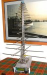
Lots of different types: the photo below is of a Watkins Johnson broadband dual/linear polarised directional Yagi i.e. it is equally sensitive to both horizontaly and verticaly polarised signals - can be used to receive both at the same time, or just one of either, or when both element array pairs are connected does a good job receiving circular/elyptical polarised signals). This Yagi offers 2.8dBi - 7.1dBi gain from 152.00Mhz - 1.370Ghz, with a average gain of just under 5dBi across the same bandwidth

That is jolly useful extra gain, but the real beauty of directional antennas?: they are quite deaf to signals (in or out of bandwidth) that arrive from all directions, except the direction to which they are pointed, and consequently they introduce a lot less rf noise to the receiver.

End result: a stronger and less noisy (quieter) signal for your receiver to deal with and demodulate ..... has to be a good thing(?).

While this antenna is a pro made mil spec example made of stainless steel (and dual polarised - you only need a vertical polarised i.e. single plane), they are easy DIY projects. Aluminium tubing from DIY or hobby shops does fine, and the internet has quite a few "on-line calculator" pages - just fill in the upper and lower frequency your Yagi needs to work on, the gain you would like to have, and the program throws out the number of elements needed and the spacing between the elements. Also, if you do decide to build one of these: while reducing the element diameter as they become shorter and the resonant frequency increases (as has been done with this antenna), does improve antenna factor and gain, in a receive only antenna where VSWR tends not to be a big issue, the benefits generally don't justify the extra work (and cost) involved - follow through the entire construction with a single suitable element diameter and all will be fine. And last but not least - take note when choosing an on-line calculator to use to get dimensions for your DIY Yagi, whether or not it is calculating for a Yagi that has it's elements isolated from the boom, or as in this example, provides dimensions for a Yagi with elements in electrical contact with the boom: forgetting to factor this into the design can have a significant impact on your antenna performance.

To give you an idea of size I took the picture alongside a WJ-8700 receiver - the antenna is 35" (wide at base element pair) x 55" (high to top of blue cap)

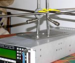
The purpose of the 2 x N-type connectors(?): to facilitate horizontal or vertical polarised signal reception, or when both are connected at the same time (through a mast mounted combiner), to provide horizontal & vertical reception concurrently, or, reception of left and/or right handed circular polarised signals.

NOTE TO MODERATOR - these pic's loaded a lot bigger than I anticipated - by all means halve their size if you wish.
 

Attachments

  • YAGI 1.jpg
    YAGI 1.jpg
    63.6 KB · Views: 587
  • YAGI 2.jpg
    YAGI 2.jpg
    69.2 KB · Views: 602
Last edited:

jackj

Member
Joined
Jul 19, 2007
Messages
1,548
Location
NW Ohio
Fredva

snip

The last thing to keep in mind about these figures, is that like the “500 watts” or "1200watts" figure that manufacturers started to play on in the 1980's/1990's, by sticking them prominently on “ghetto blasters”, they can be subject to manipulation. One way that enabled ghetto blaster manufacturers to get away with such extravagant output claims, was the way they measured "output" - they would quote all the energy released from the amp stage capacitors at a peak volume moment for a given frequency - but what they never said was that the peak volume moment lasted perhaps 2 or 3 millisec's and was only at a given frequency (which was an audio bandwidth of a few hertz at most) - and then all the energy from the cap's was spent. Hardly an accurate indicator of across the board performance, or general audio quality!

snip

The main problem with ratings for consumer-grade products is that the measurements are made by the marketing department, not by engineering. I have an air compressor with a motor that is rated at 3.5 hp. But that motor rating is just before rotor stall, not continuous output power. I don't know of any way the average consumer can determine if a spec is honest or not, all I can say is that if the spec is really good but the price is really cheap then the spec is a lie.
 

benbenrf

Member
Joined
Mar 27, 2009
Messages
287
Location
United Kingdom
The main problem with ratings for consumer-grade products is that the measurements are made by the marketing department, not by engineering. I have an air compressor with a motor that is rated at 3.5 hp. But that motor rating is just before rotor stall, not continuous output power. I don't know of any way the average consumer can determine if a spec is honest or not, all I can say is that if the spec is really good but the price is really cheap then the spec is a lie.

Jackj - exact same analogy, and very misleading .... yer, when the motor torque is maxed out!

You get spec's and you get spec's, then you get damn lies - your understanding of the theory quickly enables you to recognise the "creative marketing" from "genuine spec's".
 
Last edited:
Status
Not open for further replies.
Top