an39511
Member
Delete
Last edited:

Mike.. I've built a cable using your method, and another one using a 3.3k ohm resistor. Both are providing great audio from the rear jack. I am however getting a slight high pitch buzz.. similar tone to a ringing in the ear. any leads on how to eliminate this? Thanks
Adam
Mike G D
That being said, I don't think most people who pay $600 for this scanner (I bought two) expect to have to go through this process to be able to use line-in feeds. I suspect, like others, that this issue will be handled by the new Siren application when it is available, but I wish Uniden (I realize Paul is under certain constraints), so what I mean is Uniden as a corporation, would just come out and tell us what they have planned.
If the new Siren application takes care of this, great, wonderful, tell us that is what is planned, and I am sure everyone will patiently wait. That is the least we can expect for this 536HP scanner which everyone waited for almost 3 months.
A possible plug and play solution?
Telco & Multimedia Ground Isolation Transformer - 3.5mm M/F - Computer Cable Store™
A possible plug and play solution?
Telco & Multimedia Ground Isolation Transformer - 3.5mm M/F - Computer Cable Store™
I am just trying to toss out some pre-made options for some folks.
The problem is I assume many people may use the systems very differently.
User #1 may want to connect the audio for streaming, but not really care about listening to the scanner. User #1 may be able to listen the scanner via the sound card input and use the computer to listen.
User #2 may want to connect the audio for streaming, but wants to listen to the scanner audio full time or some times. The the issue is User #2 cannot use the scanner volume to modify or change the speaker level. In this case a separate amplified speaker might be needed in this case.
User #3 may wan to connect the audio to a mixer for steaming or patching into a sound system of some sort.
There are probably user #4-#X??
This is why I tossed out the idea for Uniden to come up with some form of solution that is blessed by them and works. Yes the user community can come up with a solution, but why should we have to.
Hopefully Uniden will learn from this issue and put back a fixed line level output in future scanners.
I am guessing that the line level output was removed because of the built in recording capability and Uniden assumed that nobody would want or need a line level output, however, this is does not appear too be the situation.
Again, I plan on interfacing a Motorola HSN1006A to both my 996XT and the 536HP. I have these currently connected in just a passive mode as an external speaker, however, I expect that there may be some issues when I go to connect the Motorola speaker up in amplified mode with the common ground.
I would be surprised if Uniden did not plan on using the USB port for audio data for PC input; as you've said, and I believe this likely, they (Uniden) most likely are working on firmware and/or software support to allow this and the hardware is likely designed accordingly.
That having been said, because so many were already trying to connect their PC audio input to the scanner and running into the problems using the BTL external speaker output, I thought it best to try to clarify the issues and then give a simple circuit for actual use to do this in the interim.
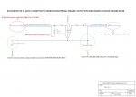
The circuit I described should not cause any damage to the BTL amp as it isolates ground by a pretty high resistance. The pot value can be increased to pretty much any value you have available and the same goes for the value of R1; what you want is the full value of R1 plus R2 (the pot) to be roughly a minimum of 20K and more is fine. At full level into a relatively low impedance mic input (say, 200 ohms or so) would present the most "risk" but the value of R1 protects against that. At the opposite extreme, at lowest level, the value is approximately the full value of the pot plus the value of R1 so with the presented values that is 30K between the BTL tip line and ground which should be fine. Again, these values can be increased if desired for extra "protection" and the circuit should still work ok.
As you've said, once the digital audio link is up and running, using the external speaker jack for connection to a PC is negated for the most part. But you never know when a need may come up in the future for whatever reason and it is always best to be informed and prepared just in case.
-Mike
Mike_G_D,.
Have you run into and hear the digital cross talk/switching noise on the external speaker output yet?
My radio has a noticeable digital cross talk/switching noise once the squelch unmutes. It is there during pauses in conversations and is a bit more obvious once the transmission stops and before the scanner resumes scanning.
It is kink of a function of the external speaker as how easy it is to hear. The speaker efficiency and speaker frequency response and make this noise more or less apparent.
If you want to sample this easily, assuming your hearing is not compromised in the higher frequency bands, plug a pair if earbuds into the external speaker connection point with the volume turned WAY down. The slowing increase the volume until you get to a comfortable listening level and you should easily hear the noise before the squelch mutes.
This noise may make it through to sound cards and recordings depending on the volume levels needed and other factors. Not sure it can easily be filtered out after the fact and if the Uniden "headphone" repair will address this issue??