Build your own AntennaCraft ST2 Scantenna

Status
Not open for further replies.

jjlongworth

Member
Joined
Aug 10, 2012
Messages
29
Location
Farmington, CT
I've received some great feedback on my post for building a Monitenna. I've also received a couple of requests for similar plans for a Scantenna.

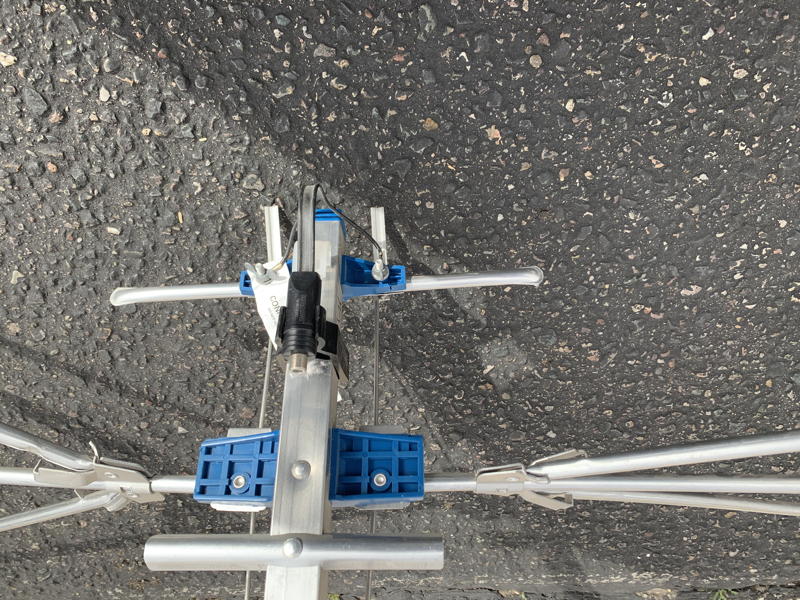
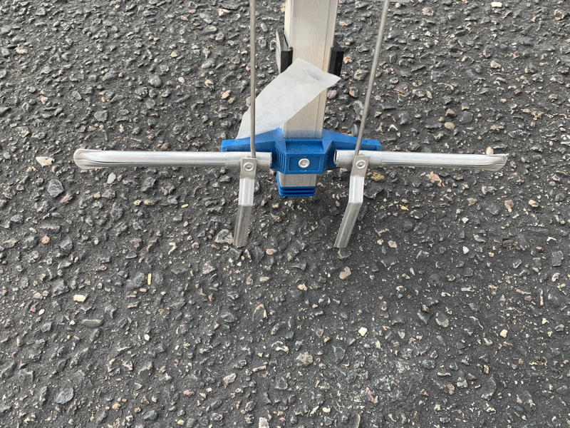
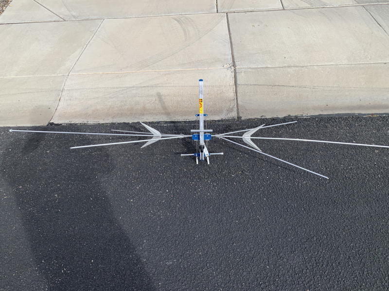
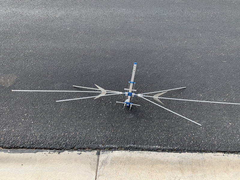
I don't own one. So, the next best thing is to build my own (I refuse to pay eBay prices). I have scoured the internet and download a ton of photos of the original along with the AntennaCraft documentaiton. I've got enough images that I was able to bring the images into Adobe Illustrator and draw the important parts to see how it is assembled. What's really interesting is how many I have found, in photos, that are assembled incorrectly! I even found a YouTube video where a guy cut one up to make a TV antenna out of it!

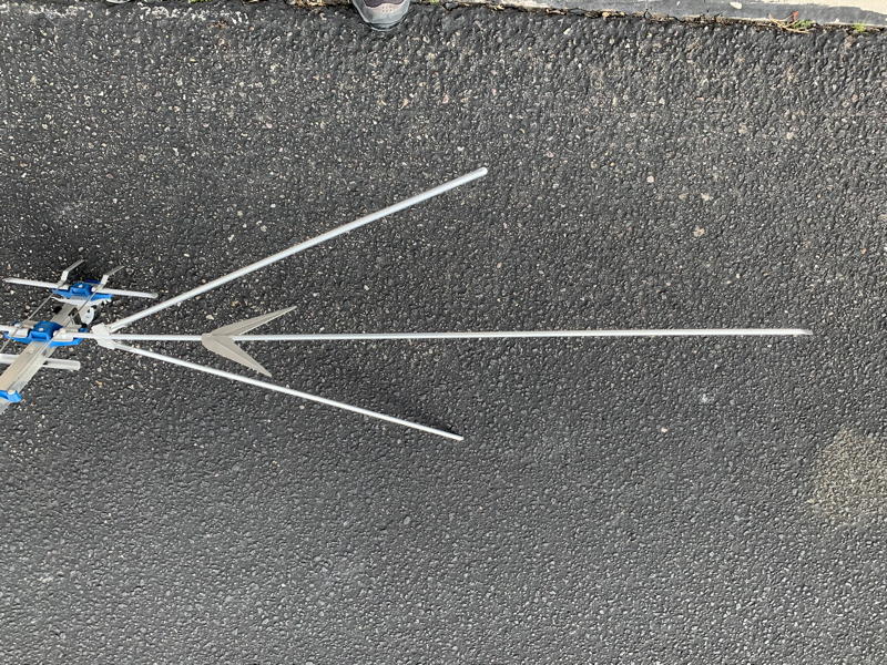
I think I've got the proportions pretty close. I'm able to scale it to get rough dimensions based on some assumptions. However, it is almost impossible to get precise dimensions. I've created the attached drawing which identifies what, I think, are the critical dimensions. Each one is identified with a corresponding number and there is a table with matching numbers. If you have access to an antenna and can provide some, or all, of the dimensions, I will get to work on writing a similar document. I'll take the dimensions however it's easiest for you to provide them: you can scan the form and post it, email it or just post the corresponding number and dimension. The bulk of this antenna will be based on the Monitenna since the center portion is very similar.

BTW - For those who are interested, I am working on revision D of the Monitenna document. I've found some grammatical things and I will be making some suggestions for sealing the elements and insulator.

Thanks
 

Attachments

  • Scantenna Dimensions doc.pdf
    179.9 KB · Views: 900

N9JIG

Sheriff
Moderator
Joined
Dec 14, 2001
Messages
5,854
Location
Far NW Valley
The longest vertical elements on the ST-2 are about 48 inches each, the other 4 elements are somewhat less.

The boom length is 20 inches.

If I can get into my attic later today I will try to measure the rest of the elements.
 

N9JIG

Sheriff
Moderator
Joined
Dec 14, 2001
Messages
5,854
Location
Far NW Valley
I know you are kidding but to tell the truth, the exact length of the elements of a scanner antenna are not critical, they just have to be in the ball park, just like horseshoes and hand grenades. My rule of thumb is a piece of metal up in the air usually beats a better antenna on the ground. The coax quality and length is more critical in most instances.

Since the antenna is designed to (only) receive on a wide array of frequencies the actual element is usually designed for about the center of the range. The ST-2 is a multi-band antenna with multiple dipole elements tied to a common feedpoint, each element specified for a large range of frequencies (30-50, 108-174, 400-512, 800-950).

The main vertical elements were designed for the 30-50 MHz. low band. Assuming they were measured to work best on the center of that band (roughly 40 MHz.) trimming them of or adding a couple inches to each is not going to make a whole lot of difference. Same goes for the 4 VHF High and Air elements. It is a little more critical on the UHF/800 elements as they have less wiggle room to work with. The diameter of the elements helps as well, one would have worse results if the elements were replaced by wire at the same lengths.

I put this part in bold, it is the most important part of the post:

I doubt most scanner uses would see any difference with a +/- 25% length change on any element absent precise measuring equipment, assuming the coax used and location are the same.

I had an ST-2 in the attic of my old house in Illinois that the top long element (with UHF spikes) was broken off at the hinge. I used it for a couple years in that fashion and then removed the matching element below it, effectively making it an "X" shaped antenna. It worked just as well as the other fully equipped ST-2 I had in the attic at the same time and I noticed no difference before and after the remaining long element (with UHF spikes) was removed.

I have thought about making a similar antenna, using a set of elements on a center beam similar to this. The genius of the ST-2 design is that the main elements share a common center point, keeping it more omnidirectional than if they were arranged side by side.
 
Joined
Mar 30, 2019
Messages
295
I doubt most scanner uses would see any difference with a +/- 25% length change on any element absent precise measuring equipment, assuming the coax used and location are the same.

Until distance becomes one of the factors... Just sayin'...
 

N9JIG

Sheriff
Moderator
Joined
Dec 14, 2001
Messages
5,854
Location
Far NW Valley
I brought one of my ST-2's down from the attic and measured it out.

Edit: I did not see your document, so I remeasured as per your request. Here are the measurements you requested:
Edit 2: Fixed 13, 14.

1: 7 7/16
2: 9 1/2
3: 5 1/2
4: 5
5: 3
6: 5 9/16 overall, 2 3/4 from rivet to end
7: 7/16
8: 27 7/16
9: 48 3/4
10: 3
11: Element is 4 3/4, the distance from the rivet to the far end is 4 1/3, and 1/2 from rivet to short end
12: 2 7/16
13: 9/16
14: 27 5/8 (but varies up to a half inch or so depending on flex)

The mast is 20 inches long plus about 1/2 inch for the plastic plugs at each end for a total length of 21. The elements are about 3/8 in diameter.

Photos to follow
 
Last edited:

jjlongworth

Member
Joined
Aug 10, 2012
Messages
29
Location
Farmington, CT
Hi Rich - Thank you very much! This is exactly what I was looking for... I will start working on plans in the next few days.

You commented that item #6 is probably a counterpoise. It's been a long time since I studied antenna theory, but I suspect you are correct. The manual (see attached) refers to this as Omni Directional antenna. However, wouldn't the presence of a counterpoise make the antenna somewhat directional? I'm out of my depth here, so I'd be interested in hearing thoughts on the physics.

Also, one thing that I noticed in your photos is the orientation of the small elements on the front elements. The manual refers to these as the Legs and the Front Main Boom Elements. During my research, I found photos showing them in every orientation imaginable. In their defense, the manual is not very clear, but it does state: "Position the legs on the smaller front elements outward, so they line up with the elements under them." I also found a post from someone who actually called AntennaCraft looking for clarification. Here is the factories response: "For this product, both parts should away/perpendicular from the boom."

Many thanks again for the effort. If there are any dimensions I've forgotten to ask for or if you find that your dimensions differ (due to tolerances etc.), please let me know.

Jim
 

Attachments

  • ST2_Manual.pdf
    373.2 KB · Views: 307

N9JIG

Sheriff
Moderator
Joined
Dec 14, 2001
Messages
5,854
Location
Far NW Valley
Yeah, they probably should be vertical rather than horizontal.

I am unsure about whether it actually is a counterpoise or what the proper term for that piece is. It is connected directly to the boom so is at the same potential as ground. I suspect it does tend to reflect the front and leg elements somewhat. I suppose it it there to correct the impedance somehow.

Again, the exact length of the various elements is not particularly critical, just get them in the ballpark.
 

DoubleMDouble9

Newbie
Premium Subscriber
Joined
Aug 22, 2013
Messages
5
Location
Worcester, Ma
This is what I got, I also sent you a ton of pics to your email.
1, 7 1/2
2, 11
3, 5 1/2
4, 4 3/4
5, 2 3/4
6, 5 1/2
7, 5/8
8, 27 1/4
9, 48 1/4
10, 3
11, 5 5/8
12, 3
13, 1/2
14, 25
 

jjlongworth

Member
Joined
Aug 10, 2012
Messages
29
Location
Farmington, CT
If it’s convenient, I neglected to ask for the dimension between the centerline of the vertical element and the centerline of the counterpoise. There is also a number fumble: I think what you’ve shown as 13 is actually 14
 

N9JIG

Sheriff
Moderator
Joined
Dec 14, 2001
Messages
5,854
Location
Far NW Valley
If it’s convenient, I neglected to ask for the dimension between the centerline of the vertical element and the centerline of the counterpoise. There is also a number fumble: I think what you’ve shown as 13 is actually 14

Transcription Error, I fixed it in my post.

The distance from the vertical element and counterpoise centerlines is 1 3/4 inch.
 

jjlongworth

Member
Joined
Aug 10, 2012
Messages
29
Location
Farmington, CT
Wow! Thank you Rodney and Rich! I appreciate the effort.

The dimensions and photos should provide everything I need to start plans. I'll start by drawing everything in AutoCad this week. I'm guessing it will take me another 2 - 3 weeks to build and doument the process. It really depends on how much free time I can carve out since I'm still among the working.

Thanks again,
Jim
 

Ubbe

Member
Joined
Sep 8, 2006
Messages
9,574
Location
Stockholm, Sweden
The "legs" should be in parallell to the main front elements and are bent so they will be positoned a bit away from the front elements which are 800Mhz and the shorter legs are the 900Mhz elements.

The number 6 elements sits close to the transmission line, the two wires that goes to the balun, and are probably a mechanical frequency filter to reduce the signal at a particular frequency, maybe FM broadcast, that could be at it's maximum at that point in the transmission line. It's too far away from any UHF element to work as a counterpoise. I've seen similar solutions on antennas that are advertised as having cellular LTE filters, which is at 800MHz in europe. One way to be more sure of its function would be to sweep the antenna using a VNA and then twist the #6 so it gets parallell to the boom and do another sweep.

The VHF/UHF bands are somewhat directional due to the design and are confirmed from users that experiance level changes in the received signal depending of in what direction the antenna are pointed. S-UHF, and probably also low-VHF, should be less directional as it is more or less a standard 1/2 wave dipole design.

/Ubbe
 

trp2525

Member
Joined
Mar 31, 2010
Messages
1,299
FYI for those who may have missed the thread here on RR, it looks like you may soon be able to purchase a brand-new ST2 Scantenna heavy-duty clone instead of building your own. According to the information in this RR thread (which includes 6 copyrighted photos of the prototype clone antenna) the antenna will be "built like a tank" and use heavy wall aluminum tubing, aluminum plates, stainless steel hardware and will be handmade: New Antenna Coming Soon based on Old Favorite.
 

jjlongworth

Member
Joined
Aug 10, 2012
Messages
29
Location
Farmington, CT
Ubbe - Thank you for your thoughts regarding the function of #6 element. It makes sense to me (sort of).

Trp2525 - Thank you for passing this along. I had not seen this thread. It will be interesting to follow it's availability. My guess is that it won't be inexpensive. This is not meant as a criticism because I know this is only a prototype. However, the poster mentions (and the photo shows) lots of stainless hardware. Stainless and aluminum don't mix. Here is a link to an article I found while confirming it: Stainless Steel & Aluminum: Why You Shouldn't Use Them Together and Proper Precautions To Take If You Do | Albany County Fasteners

There is plenty of room in the pool.... I will continue along the path of writing a document which will allow others to build their own if they are interested in experimenting. I'm almost done with the CAD drawings and will be starting the build soon.
 

jjlongworth

Member
Joined
Aug 10, 2012
Messages
29
Location
Farmington, CT
I assume you are suggesting copper because it's easy to work with and you could solder all of the pieces together. If so, it would make assembly a breeze. I would also prep and paint it to avoid oxidation. Electrically it should work great.

My biggest concern would be weight. The copper is soft but heavy. In a storm, I suspect it would be too soft to handle it's own weight. In an attic, I think you'd be ok.
 
Status
Not open for further replies.
Top