• To anyone looking to acquire commercial radio programming software:

    Please do not make requests for copies of radio programming software which is sold (or was sold) by the manufacturer for any monetary value. All requests will be deleted and a forum infraction issued. Making a request such as this is attempting to engage in software piracy and this forum cannot be involved or associated with this activity. The same goes for any private transaction via Private Message. Even if you attempt to engage in this activity in PM's we will still enforce the forum rules. Your PM's are not private and the administration has the right to read them if there's a hint to criminal activity.

    If you are having trouble legally obtaining software please state so. We do not want any hurt feelings when your vague post is mistaken for a free request. It is YOUR responsibility to properly word your request.

    To obtain Motorola software see the Sticky in the Motorola forum.

    The various other vendors often permit their dealers to sell the software online (i.e., Kenwood). Please use Google or some other search engine to find a dealer that sells the software. Typically each series or individual radio requires its own software package. Often the Kenwood software is less than $100 so don't be a cheapskate; just purchase it.

    For M/A Com/Harris/GE, etc: there are two software packages that program all current and past radios. One package is for conventional programming and the other for trunked programming. The trunked package is in upwards of $2,500. The conventional package is more reasonable though is still several hundred dollars. The benefit is you do not need multiple versions for each radio (unlike Motorola).

    This is a large and very visible forum. We cannot jeopardize the ability to provide the RadioReference services by allowing this activity to occur. Please respect this.

Can someone help me tune my homemade dipole?

Status
Not open for further replies.

mofugly13

Member
Joined
Dec 1, 2014
Messages
4
Location
San Francisco, Ca
Hello all. I'm brand new here. I'm a rank amateur when it comes to radio tech. But I'm very mechanically inclined and like to build stuff myself whenever possible. Sooo...


I was hoping someone could help me out with a homebrew dipole antenna installation.

I have a hunting cabin in Northern Ca, and recently decided to set up a cb base station there mainly so I can communicate to the cabin from my hunting rigs from (almost) anywhere on the ranch. I have a CB already installed in my Samurai, and this weekend I tried to install a homebrew dipole on the cabin. After getting it installed, I had an SWR of 3:1 on both channels 1 and 40. Here's a photo of the antenna setup where the coax connects:
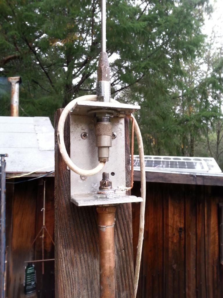
20141130_122506_zpsmgclxaaf.jpg


I'm hoping it's pretty self explanatory, but here's how I made it- I used a piece of aluminum channel and mounted a 102" stainless whip to the top using a PL259 antenna connector. For the counterpoise I used a piece of 1/2" copper tubing, 102" long, and it is secured to a threaded hole in the channel with lock nuts on either side to make good contact with the aluminum channel. Then, for good measure, I created a jumper from the PL259 connector shield to the copper pipe via a solid copper wire and a copper bolt I soldered into the end of the MIP-tubing adapter. I used anti-oxidant conductive grease on all the connections, making sure not to create a short between the ground and center conductor of the coax. Then there's about 22' of RG8x running to the cabin where I was attempting to use an old Cobra 29Plus as a base station.

At the cabin, there is extremely limited cell access, and therefore, no internet access, so on site troubleshooting was out. However after some reading and research today I think I have some potential issues, and it would be great if anyone who knows about these things could pitch in their 2 cents.

At the connection of the coax to the antenna, the coax runs down, parallel to the antenna for about 4' before it runs horizontally to the cabin. I think the coax needs to run horizontally directly from the connection at the antenna for a minimum distance before making any vertical turns?

My antenna is mounted on a post that stands about 7' off of the deck of the cabin, and therefore, my radio is mounted only about 3' vertically below the center connection of the antenna. Do I need to get the entire antenna up higher than the radio to get a better swr?

The cabin is built on a steep hillside, and where the antenna is right now, it's on the downhill side of the cabin and is at a higher elevation than 80% of the rest of the ranch. Rx is good, I took a ride in my Samurai, and called out different landmarks around the ranch as I got to them and my wife could read me loud and clear out to about 3.5 miles, which is as far as I went. However, due to the 3:1 swr and the fact that for some reason the Cobra 19plus would not transmit any sound, we couldn't do real-time radio checks. She just wrote down the landmarks as she heard them so I could see how far she could hear me.

What should I do to lower my swr?
 

jaspence

Member
Premium Subscriber
Joined
Mar 21, 2008
Messages
3,041
Location
Michigan
Dipole

A dipole antenna does not use radials. Each side is about 1/4 wave length. I see a couple of problems. All dipoles I have made use the same material on both sides, and the the legs (antennas) are separated by either air or a non conductive material. You need another whip for the bottom leg. The center of the coax goes to one leg and the ground to the other leg. I usually attach the coax directly to each leg and then secure it and seal it rather than try to use a connector. The coax should be at a right angle if possible, but I made a vertical mobile 2 meter dipole in plastic pipe that worked well with the lead bent very close to the lower leg.
 

zz0468

QRT
Banned
Joined
Feb 6, 2007
Messages
6,034
Start by putting a dummy load on the coax, at the PL-259 in the photo, and then measure the SWR. If it's not 1:1 on every channel, fix or repair the coax.

The picture is clear on what you're trying to do. What's not so clear is whether or not the connector through to the upper whip is really insulated from the other side. Take an ohm meter, and measure the coax at the radio end from center conductor to shield.

Make those two measurements, and report back for the next step.
 

prcguy

Member
Premium Subscriber
Joined
Jun 30, 2006
Messages
16,632
Location
So Cal - Richardson, TX - Tewksbury, MA
Looks like he used an SO-239 to 3/8-24 adapter and if there is an insulator between the top whip and mount that part should be ok. Its best if the coax exits the antenna sideways for as far as possible to avoid interaction with the antenna, but I've tuned some up that looked worse than this one.

The 102" whip and equal length of copper pipe is a bit unsymmetrical since the thickness of the pipe will make it appear longer than the whip. You need to find out where it resonates to determine what to do next. If the match is better on the lower channels then the antenna needs to be a little shorter and if the higher channels are better it needs to be longer.

If it requires shortening I would take a little off the pipe first since its probably electrically longer than the whip. Another problem is a vertical dipole will be a higher impedance than 50 ohms and may never match perfectly. In free space their about 72 ohms but near the ground a little lower.

If it doesn't tune up you might be better off with two or three wires running horizontally out from the grounded mount as a counterpoise and a 102" vertical whip usually tunes up just fine with that.
prcguy

A dipole antenna does not use radials. Each side is about 1/4 wave length. I see a couple of problems. All dipoles I have made use the same material on both sides, and the the legs (antennas) are separated by either air or a non conductive material. You need another whip for the bottom leg. The center of the coax goes to one leg and the ground to the other leg. I usually attach the coax directly to each leg and then secure it and seal it rather than try to use a connector. The coax should be at a right angle if possible, but I made a vertical mobile 2 meter dipole in plastic pipe that worked well with the lead bent very close to the lower leg.
 

zz0468

QRT
Banned
Joined
Feb 6, 2007
Messages
6,034
Looks like he used an SO-239 to 3/8-24 adapter and if there is an insulator between the top whip and mount that part should be ok.

That's the part in the photo that I'm not real sure about. I don't see an insulator on the top.
 

mofugly13

Member
Joined
Dec 1, 2014
Messages
4
Location
San Francisco, Ca
Start by putting a dummy load on the coax, at the PL-259 in the photo, and then measure the SWR. If it's not 1:1 on every channel, fix or repair the coax.

The picture is clear on what you're trying to do. What's not so clear is whether or not the connector through to the upper whip is really insulated from the other side. Take an ohm meter, and measure the coax at the radio end from center conductor to shield.

Make those two measurements, and report back for the next step.

Thanks zz, I will try that with the dummy load next time I'm up at the cabin, probably the end of this month. I'll also check resistance between the center conductor and shield at the radio end. If all is well, should I see 50 ohms or an open circuit?

Looks like he used an SO-239 to 3/8-24 adapter and if there is an insulator between the top whip and mount that part should be ok. Its best if the coax exits the antenna sideways for as far as possible to avoid interaction with the antenna, but I've tuned some up that looked worse than this one.

The 102" whip and equal length of copper pipe is a bit unsymmetrical since the thickness of the pipe will make it appear longer than the whip. You need to find out where it resonates to determine what to do next. If the match is better on the lower channels then the antenna needs to be a little shorter and if the higher channels are better it needs to be longer.

If it requires shortening I would take a little off the pipe first since its probably electrically longer than the whip. Another problem is a vertical dipole will be a higher impedance than 50 ohms and may never match perfectly. In free space their about 72 ohms but near the ground a little lower.

If it doesn't tune up you might be better off with two or three wires running horizontally out from the grounded mount as a counterpoise and a 102" vertical whip usually tunes up just fine with that.
prcguy

Yes, I did use an SO-239 to3/8-24 adapter with the insulator. If I can't get this antenna tuned, I'll switch to radials. If I do that, I'll need to find a new location for the antenna, though. Really hoping to get this dipole to work. The rg8x I used was, well, used. I'll try to get ahold of some fresh coax to bring with me later this month when I go back. What would be the BEST coax to use for an installation like mine?

Thanks for all the input guys, it is very appreciated.
 

sloop

Member
Joined
Jul 19, 2008
Messages
362
Location
Lewisville, NC
mofugly13, google 'a stealthy homebrew vertical dipole antenna using mobile cb antennas' by scott wolfington. He has done what you attempted. I made one for my barn and it works. Low SWR trick is to use the same antenna on each side of the dipole for impedance matching.
 

millrad

Member
Premium Subscriber
Joined
Apr 14, 2004
Messages
253
Location
Connecticut
The easiest solution seems to be adding an antenna tuner at the radio end of the connection. You also might try lengthening or shortening the coax run, since the wavelength of the feedline can also effect the impedance match.
 

jaspence

Member
Premium Subscriber
Joined
Mar 21, 2008
Messages
3,041
Location
Michigan
Dipole

An antenna tuner will not fix the real problem, it will only fool the radio into thinking it is ok. You can make a dipole out of any two equal pieces of metal. Most of mine have been 12 or 14 gauge copper wire which is easy to tune by starting a little bit long and cutting equal amounts off both legs. A good swr meter at the transmitter end is the best way to accomplish the tuning unless you have an antenna analyzer. If you check at the radio end with an ohm meter, you should see an open circuit. Measuring impedance for an antenna cannot be done with a regular ohm meter, it requires an antenna analyzer.
 

jonwienke

More Info Coming Soon!
Joined
Jul 18, 2014
Messages
13,409
Location
VA
You also might try lengthening or shortening the coax run, since the wavelength of the feedline can also effect the impedance match.

Not really. Changing the phase relationship between the transmitted and reflected waves by altering coax length can fool an SWR meter into displaying an artificially low SWR, but it will not help you get out any better. You can verify this by connecting the SWR meter directly to the antenna. Changing coax length can alter the SWR reading at the radio end of the coax, but it will not change the SWR reading at the antenna end.
 

AC9KH

Member
Joined
Nov 5, 2014
Messages
131
Location
Northern Wisconsin
Many folks have responded with good suggestions. But I'll offer my 2 cents anyway.

Your dipole is probably not balanced and the ground element is more than likely electrically longer than the 1/4 wave whip because of the diameter of it. A dipole should be a balanced load and coax is an unbalanced feedline. You'll have high losses in the coax no matter what you do, and ideally feeding your dipole with ladder line would be better because ladder line is a balanced feedline. But that would require more equipment at the radio to make it work, like a tuner with a balanced output.

You mentioned checking the antenna for 50 ohm - well, that won't work. That 72 or 73 ohm impedance that a dipole has, and the 50 ohm impedance that coax has is AC impedance, not DC resistance. So you can't measure it with an ohmmeter.

I would start by taking your coax off there and rerouting it so it comes into the dipole in a perpendicular fashion. See if that improves SWR any, as you may be getting common mode current on the shield of the coax. Then go to shortening your ground element a bit at a time and see if you get a better match. It might end up quite a bit shorter than the whip because of different types of elements used.

It's going to be really hard to get a 1:1 match with coax feeding a vertical dipole because even with the ground element closer to the ground it won't drop the impedance of the dipole much. It's not like a horizontally polarized dipole where lowering the antenna closer to the ground will lower impedance to a closer match with your feedline. You should be able to get about 1.3:1 though. I've built several vertical dipoles for 11 meter radios and gotten them to 1.3. However, the elements on the ones I've built have always ended up shorter than the "standard" 102".

In the end I think it would be easier to convert it to an elevated 1/4 wave ground plane. You only need one radial if you don't have a lot of room and you can make that with a piece of wire. The antenna will be somewhat directional with only one ground plane element, having higher gain on the side with the ground radial. But it will be easier to match your feedline. And with the inherent high losses in 50 ohm coaxial cable, I think it would be the better option.
 

mofugly13

Member
Joined
Dec 1, 2014
Messages
4
Location
San Francisco, Ca
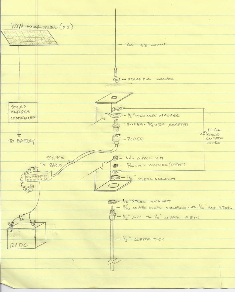
Thanks for all the responses guys. I think the first thing I'll do when I get back to it is extend the feed line horizontally from the antenna and see how that changes things, then proceed with putting a dummy load on the coax and checking things out. FWIW, heres a schematic of my setup:

Scan_Pic0019_zps74fd080e.jpg
 

RC286

Member
Joined
Oct 25, 2013
Messages
138
Location
Winnipeg MB
how long is the copper pipe? Velocity factor of copper is different than that of steel. Your counterpoise will likely be closer to 108" than 102"
Also keep in mind that the length of the bracket or wire (whichever is shorter) will be part of the electrical length of the counterpoise.
The counterpoise starts right at the SO-239 where the coax ends. From there everything connected is antenna.
\
 

AC9KH

Member
Joined
Nov 5, 2014
Messages
131
Location
Northern Wisconsin
Could try cutting the copper pipe and sweat a 90° elbow into it to make a ground plane out of it. The impedance of a ground plane antenna is about 36 ohm and usually bending the radials down to about 30-45° increases the impedance to around 50 ohm for a perfect match. The length is not that critical for a ground plane antenna as long as one radial is at least 1/4 wavelength. Then you can end feed it with your coax with no problem.

Nice drawing!
 

cmdrwill

Member
Joined
Mar 30, 2005
Messages
3,984
Location
So Cali
And, the bottom half of the dipole, the copper pipe, is NOT in the clear. It needs to be clear of any thing, even the wood fence. Even then the SWR would be close to 2:1 because a true dipole is about 75 ohms.

Better is some radials off in both directions along the fence, instead of the copper pipe. They can be 'bent down' for best SWR.
 

mofugly13

Member
Joined
Dec 1, 2014
Messages
4
Location
San Francisco, Ca
Point taken cmdrwill. How do attic mounted dipoles work when mounted against framing lumber? I think I may need to completely relocate the antenna, but I'm really trying to keep it low profile. What's the longest length of coax that is practical to use before signal loss becomes too great? A longer coax would give me more options on mounting location.
 

zz0468

QRT
Banned
Joined
Feb 6, 2007
Messages
6,034
How do attic mounted dipoles work when mounted against framing lumber?

They work just fine. They don't always come out to the calculated length, though.

I think I may need to completely relocate the antenna, but I'm really trying to keep it low profile.

I wouldn't be so quick to blow off what you've already done. Honestly, I don't see any obvious reason why it wouldn't work, other than proximity to other objects detunes it a bit.

What's the longest length of coax that is practical to use before signal loss becomes too great? A longer coax would give me more options on mounting location.

Google "coax loss calculator", and you'll find several web sites where you can select a type of coax, plug in the length and frequency, and it will tell you what the loss is, in dB. 3 dB is half the power, which is not as severe as it sounds, but you probably want to try to keep the line loss to a dB or less. Don't sweat it if the run you want to make is 1.2 dB, or something like that. Pick RG-8, RG-213, or LMR400 cable. I've never been a fan of 8X.

As to the antenna, it's hard to determine what's actually wrong without running a few tests. It could be stupidly simple like a bad coax run, or a short at that SO-239 to 3/8 adapter. Or, it could be proximity of the antenna to the ground, or a combination of all. Try replacing the lower part of the dipole with a piece of wire that you can trim, and if cutting it shorter makes the SWR go down, then maybe trimming the copper pipe would work.

The trouble with that frequency range is that interaction with objects tends to occur within a wavelength or two, and at 27 MHz, that's about 36 feet. It's not impossible to deal with, it just means you can't take a rough estimate, like 102", and expect it to work out of the gate.

Nice drawing, btw.
 
Status
Not open for further replies.
Top